ZW3D Connection Pipe Tutorial
grabcad
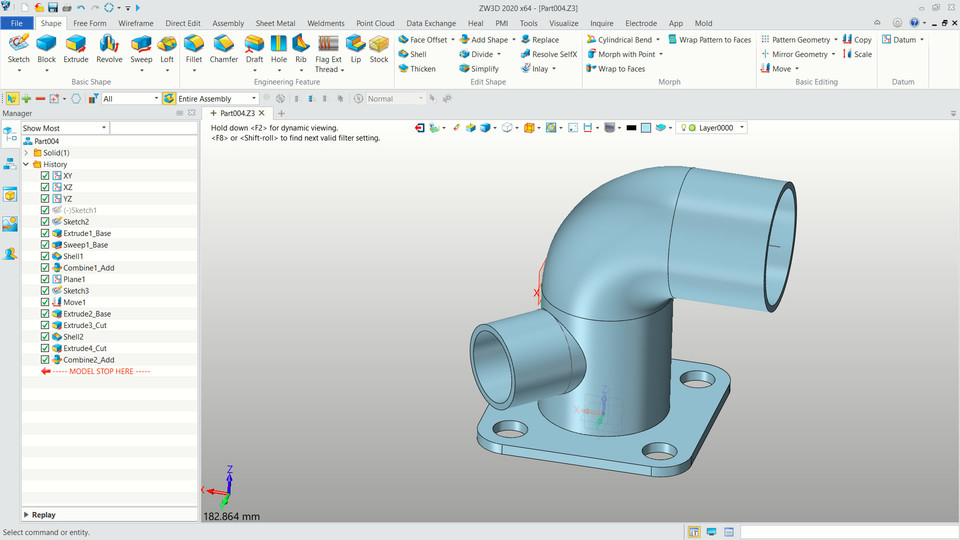
Mastering ZW3D to Design Connection Pipes is a Highly Valuable Skill. First, Open ZW3D and Start a New Project. Select "Create" from the Main Menu, then Choose "Assembly." This will allow you to work with multiple components at once. Next, Create a New Part in ZW3D by Going to "Part" under the "Create" Menu. You Can Now Sketch the Pipe's Profile. Use the "Sketch" Tab and Draw a Simple Shape that Represents Your Connection Pipe. Now it's Time to Add Dimensions to Your Sketch. Use the Dimension Tool to Define the Length, Diameter, and Other Parameters of Your Pipe. This will Ensure that Your Pipe Fits Perfectly with Other Components in Your Design. To Create a 3D Model of Your Pipe, Go to "Part" under the "Create" Menu and Select "Extrude." You Can Now Use the Extrusion Tool to Convert Your Sketch into a Solid 3D Object. With Your Pipe Created, It's Time to Add Connections. To Do This, Simply Drag-and-Drop Other Components from Your Project Tree onto Your Pipe. ZW3D Will Automatically Create Joints and Connectors Between the Two Parts. Finally, Save Your Design and Export it as an STL or STEP File for 3D Printing or CNC Machining.
With this file you will be able to print ZW3D Connection Pipe Tutorial with your 3D printer. Click on the button and save the file on your computer to work, edit or customize your design. You can also find more 3D designs for printers on ZW3D Connection Pipe Tutorial.