Zuse inspired Z1-Z2 logic gate demonstration set
thingiverse
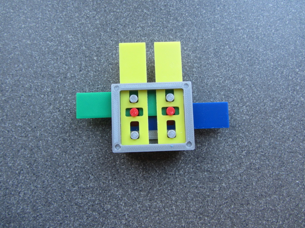
This is my interpretation of the operation of basic logic gates as they could be used in the Zuse Z1 and Z2 programmable calculators. The information comes from pages 216-221 in the book described below. The illustrations are from the patent Zuse applied for in 1936 or by the books' author. The original Z1 is designed and built between 1936 and 1941. A replica of the design is built by Konrad Zuse in 1989. The Z3 and Z4 use relays for the CPU part, so mechanical gates are probably not used there. The original described parts are simple metal strips and a pin (red, blue, yellow, green, and middle gray parts), with some guides added. In the actual machine, the parts will be different and integrated. This model is only to demonstrate the principle, not to resemble the original or replica. The book does not mention the type of gate, but it appears to be an XNOR. By rearranging parts, it can be transformed into an AND, and by substituting some parts, it becomes an OR gate. A NOT is also in there. Nowhere in the literature is mentioned what the Z1 and Z2 gates actually looked like. The 3D-rendered gates shown here are only a possibility, based on a generic description in the patent application. Also note that the definition of a "0" and a "1" isn't consistent between the different configurations. The computer machines of Konrad Zuse/Ed.: Raul Rojas. With contributions from F.L. Bauer, H.Dorsch, H. Petzold, R. Rojas, G.-A. Thurm, and G. Widiger, as well as two patent documents by Konrad Zuse ISBN-13: 978-3-642-71945-5 Springer-Verlag Berlin Heidelberg 1998
With this file you will be able to print Zuse inspired Z1-Z2 logic gate demonstration set with your 3D printer. Click on the button and save the file on your computer to work, edit or customize your design. You can also find more 3D designs for printers on Zuse inspired Z1-Z2 logic gate demonstration set .