Zuse inspired Z1 logic gate demonstration set (improved, again)
prusaprinters
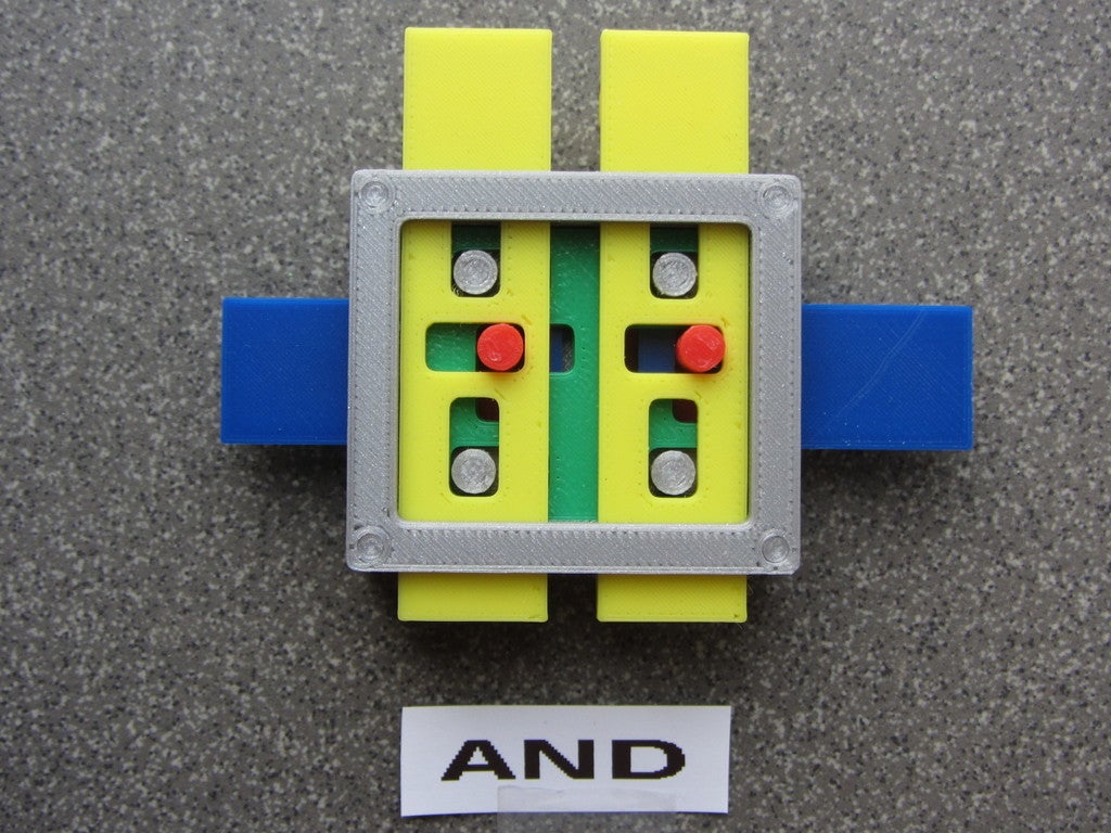
<p>This is a new version of my interpretation of the operation of basic logic gates as they could look like in the Zuse Z1 programmable calculator. The information is from pages 216-221 in the book described below. The illustrations are from the patent Zuse applied for in 1936 or by the books' author. The original Z1 is designed and build in 1936-1941. The replica/redesign is build by Konrad Zuse in 1989. The Z2, Z3 and Z4 used relays for the CPU part, so mechanical gates are probably not used here.</p><p>The original described parts are simple metal strips and a pin (red, blue, yellow, green and middle gray parts), I added some guides to make the gate work in isolation. In the actual machine the parts will be different and integrated. This model is only to demonstrate the principle, not to resemble the original (destroyed) or replica (Deutschen Technikmuseum, Berlin, Germany: <a href="https://sdtb.de/museum-of-technology/exhibitions/1256/">https://sdtb.de/museum-of-technology/exhibitions/1256/</a>). This is an improvement of <a href="https://www.thingiverse.com/thing:3366661">https://www.thingiverse.com/thing:3366661</a>.</p><p>The book does not describe the actual AND, OR and XOR gates, but based on the information this could be close to the actual parts. These elements reuse most parts of my earlier attempt, and are functionally more consistent. The main difference are the floating plates (green), one normal one for the AND and two thin ones for the OR and XOR.</p><p>Animations of the operations of these gates can be found on my site: <a href="https://fjkraan.home.xs4all.nl/mechanics/zuseGates/">https://fjkraan.home.xs4all.nl/mechanics/zuseGates/</a></p><p>The book:<br/>Die Rechenmaschienen von Konrad Zuse/Hrsg.: Raul Rojas. Mit Beitr. von F.L. Bauer, H.Dorsch, H. Petzold, R. Rojas, G.-A. Thurm und G. Widiger sowie zwei Patentschriften von Konrad Zuse<br/>ISBN-13:978-3-642-71945-5<br/>Springer-Verlag Berlin Heidelberg 1998</p><h3>Print Settings</h3><p><strong>Printer Brand:</strong></p><p>Prusa</p><p> </p><p><strong>Printer: </strong></p><p>I3 MK3S</p><p><strong>Rafts: </strong>No</p><p> </p><p><strong>Supports: </strong>No</p><p><strong>Resolution: </strong>0.20 mm layer, 0.4mm nozzle or smaller</p><h3><strong>Filament:</strong> </h3><p>Brand: Any will do. I used PLA, but any rigid filiament will do </p><p>Color: as you like it, colorful is more fun. <br/> </p><p><strong>Notes: </strong></p><p>Note all parts except the (green) c and d plates are the same for all gates. The AND has one plate (c) and the OR and XOR have two (c and d).</p><h3>Post-Printing</h3><p>Some filing can be needed to get the internal plates to fit in the fixed plate (gray).</p><p>For the OR and XOR gate, the two floating plates are the same but one must be flipped before installing. See the animation.</p><p>The input plates are yellow, the right blue plate is the clock, the left blue plate is the output. Note the gates work in two phases; first set the inputs, then apply the clock bu moving it to the right. To reset to the initial state, reset the clock plate, then the inputs.</p><h3>Custom Section</h3><p><strong>Constructing the AND gate</strong></p><figure class="image"><img src="https://cdn.thingiverse.com/assets/72/90/b0/fc/fb/ORconstruct.gif"/></figure><p><strong>Constructing the OR gate</strong></p><figure class="image"><img src="https://cdn.thingiverse.com/assets/22/e3/28/79/d8/XORconstruct.gif"/></figure><p><strong>Constructing the XOR gate</strong></p><h3>Custom Section</h3><p><strong>References</strong></p><p> </p><p>Die Rechenmaschienen von Konrad Zuse/Hrsg.: Raul Rojas. Mit Beitr. von F.L. Bauer, H.Dorsch, H. Petzold, R. Rojas, G.-A. Thurm und G. Widiger sowie zwei Patentschriften von Konrad Zuse<br/>ISBN-13:978-3-642-71945-5</p><p>Springer-Verlag Berlin Heidelberg 1998</p><p><a href="https://sdtb.de/museum-of-technology/exhibitions/1256/">https://sdtb.de/museum-of-technology/exhibitions/1256/</a></p><p>The Design Principles of Konrad Zuse's Mechanical Computers (<a href="https://arxiv.org/pdf/1603.02396">https://arxiv.org/pdf/1603.02396</a>)</p><p>The Z1: Architecture and Algorithms of Konrad Zuse's First Computer (<a href="https://arxiv.org/pdf/1406.1886">https://arxiv.org/pdf/1406.1886</a>)</p><p>Some more information on the reconstructed elements (http://electrickery.connected.by.freedominter.net/mechanics/zuseGates/)</p><p> </p><p> </p><p> </p><p>Category: Computer</p>
With this file you will be able to print Zuse inspired Z1 logic gate demonstration set (improved, again) with your 3D printer. Click on the button and save the file on your computer to work, edit or customize your design. You can also find more 3D designs for printers on Zuse inspired Z1 logic gate demonstration set (improved, again).