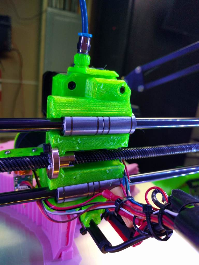
Zaribo X axis lead screw conversion
thingiverse
These are the components you'll need to convert your Zaribo 3D printer's X-axis from belt driven to screw driven. This conversion may also work for other Prusa-style printers, but verify that the distance between the Z-axis leadscrews and Z smooth rods is correct. The bearing holder mates with the MK3-style Bondtech extruder holder. If you don't have this extruder, it's easy to modify the bearing holder to fit another extruder by adding new screw holes where needed. This conversion assumes standard 8mm lead screws, which I found on AliExpress. The ones I'm using are 8mm diameter, 2mm pitch, and 14mm lead screws. This increased lead allows the print head to move at the same speed as the belt-driven system without over-spinning the motor. You'll need both the screw and T-nut for this conversion. I only found a matching pair with 14mm lead on AliExpress, but a more aggressive lead (16mm) would further reduce the need for the motor to turn faster than with the belt system. Use the Prusa calculator to find the steps/MM value you'll need to input into your firmware for the new X-axis steps/mm value. If using 14mm lead screws like I am, the value is 228.57. You'll also need two 608ZZ bearings (8x22x7). Disclaimer: This setup is experimental and a first attempt. I've been running these models non-stop for around 1.5 months without issue. When assembling the axis, it became apparent that either the models weren't perfectly aligned in CAD or the lead screw wasn't straight. The offset was not drastic, but to accommodate and keep the T-nut from binding on the axis extremes, I had to loosen one of the screws mounting the T-nut to the X-carriage bearing holder. This allowed the T-nut to align with the screw rather than the bearing holder. It may sound bad, but it makes no functional difference to the workings of the axis. The important part is that the T-nut does not move relative to the bearing holder. Another note: Due to the slight misalignment in the screw, using a rigid coupling to attach the motor to the screw forced the motor holder to move along with the bend in the screw. I had to swap this for a flexible coupling to compensate, but it has worked just fine. There are no pre-formed holes for the X-axis endstop switch because the screws used for that switch are small. You can drill and mount it to the printed part after printing and assembly or add them to the model before printing. Parts list: * Lead screw (must find a T-nut with matching 2mm pitch and #mm lead) https://www.aliexpress.com/item/304-stainless-steel-T8-screw-length-500mm-lead-1mm-2mm-3mm-4mm-8mm-10mm-12mm-14mm/32695471104.html * T-nut (https://www.aliexpress.com/item/T8-eliminate-clearance-nut-anti-backlash-nut-trapezoidal-screw-nut-pictch-2mm-lead-8mm-1pcs/32732745669.html) * Bearings (https://www.amazon.com/gp/product/B07216D1SZ/ref=oh_aui_detailpage_o03_s00?ie=UTF8&psc=1) * Other links: + Prusa Calculator: https://www.prusaprinters.org/calculator/ + Tinker Cad project with Zaribo X/Z axis mock-up: https://www.tinkercad.com/things/7QPhKkyIeCp
With this file you will be able to print Zaribo X axis lead screw conversion with your 3D printer. Click on the button and save the file on your computer to work, edit or customize your design. You can also find more 3D designs for printers on Zaribo X axis lead screw conversion.
