Z Axis Support Rod System for Ender 3 Pro with Ender Extender
thingiverse
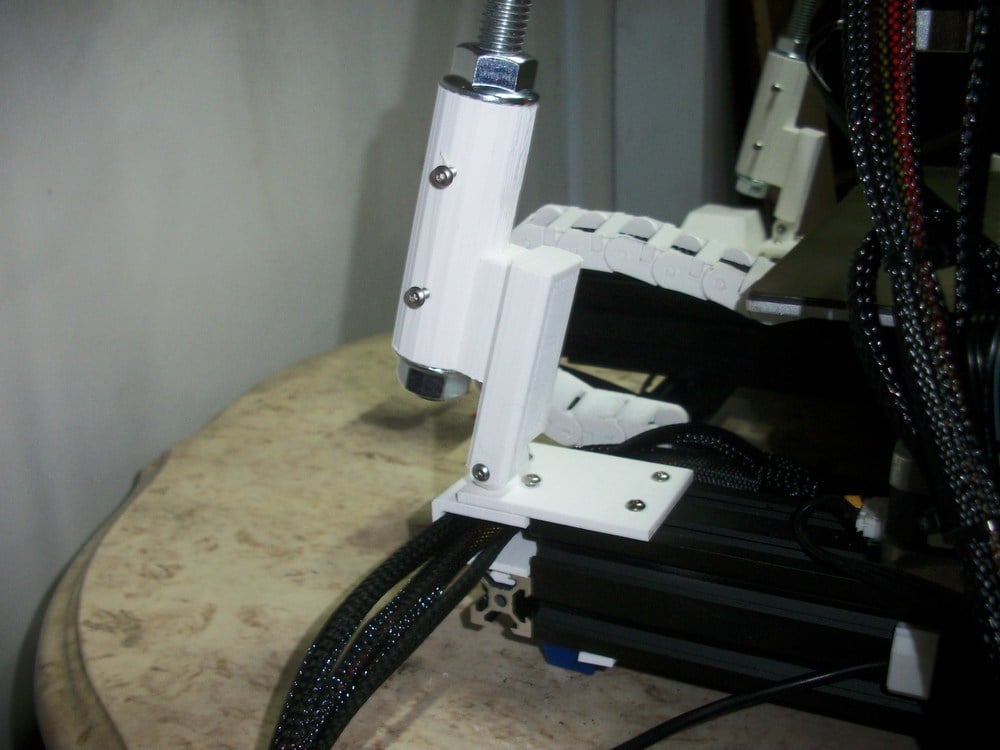
Hi everyone. This is a z axis stabilizer designed to be used with a 1/2 threaded rod (available at any hardware store near you). You will need an assortment of screws and nuts for this project. Here's a list of what you will need. -12 m3 screws 6 or 8mm to secure the rods to the mounts and to secure the mounts to the undercarriage prints. -2 1/2 inch threaded rods 510 mm long (this length depends on how high your z axis is. For mine, it is a 400 mm height, so I need 510 mm) -2 m3 25mm screws -2 m3 nuts to secure the 25mm screws -4 m4 40mm screws -4 m4 t slot nuts -4 10mm m3 screws to pair with the t slot nuts -4 m3 t slot nuts -2 nuts -4 serrated 1/2 nuts I designed these to work with a dual z axis, so the file labeled z rod block is a stand in for the spot that is green in the picture taken in my software. The pictures should show where to put everything. But here is a quick overview of how to set this up. 1. Secure one end of each rod to the left and right top side mounts by putting two m3 screws in the m3 holes and tightening them down. As you can see in the pictures, my m3 screws were too long and stick out a bit. Tighten them to hold the threaded rod in place. 2. Feed 4 six m3 screws through the bottom mounts left and right (two in each, and screw on a t slot nut to each. Do not tighten these down. Leave them just a few turns onto the screws. 3. At the bottom of each 4040 extrusion, slide the Left and right bottom mount plates onto the 4040 extrusion. Do not secure them yet. Slide them forward. 4. slide the undercarriages into place. The one for the right side is designed to be a guide for any wires you may need to redirect, so put those wires you wish to redirect into it and then slide it on. 5. Slide the left and right bottom mount plates into place, and screw them down to the undercarriages using a couple of m3 screws. Quickly rotate the screws with the t slot nuts on them to lock them in place. 6. At the free end of each threaded rod, thread the first serrated bolts on and spin them until they are about half way up the shaft. 7. Slide on the bottom mount links left and right to each shaft. you may want to use m3 screws in the holes on the links to tighten these up enough to keep them in place, but don't worry about making them really tight yet 8. Screw on the second set of serrated nuts. Do not tighten yet. 9. Using the two m3 25mm screws, secure the mount links to the mount plates with a nut on each screw. Do not tighten these up yet. 10. Slide the z rod blocks over the lead screw or lead screws and position them so that they are in line with the top side mounts. 11. Feed two 40 mm m4 screws through each mount and the block for each side and screw on loosely the t slot nuts for each screw. Position the assembly with the t screws in the grooves of the frame and free from the edges of the lead screw in the middle of it. Then quickly rotate the screw heads clockwise to lock the t slot nuts into the extrusion. 12. Back at the bottom, you can now tighten down everything, as pictured. Hope you guys find some usefulness in this upload. Explaining how to do it was more work than actually doing it.
With this file you will be able to print Z Axis Support Rod System for Ender 3 Pro with Ender Extender with your 3D printer. Click on the button and save the file on your computer to work, edit or customize your design. You can also find more 3D designs for printers on Z Axis Support Rod System for Ender 3 Pro with Ender Extender.
