XRP Catapult Launcher
prusaprinters
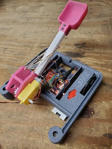
OverviewThis submission to the XRP contest is a “slip-gear” catapult add-on to the XRP robot. This mechanism gives students the ability to further advance their ability to experiment and learn with the XRP robotics platform. An example is this catapult can only provide a single shot at a time, but students may challenge themselves to allow for multiple shots. Students can also programmatically control the XRP to shoot projectiles at various targets. This model was designed to be very simple to construct by only using five printed parts. HardwareThis design is built to be incorporate parts and electronics that are easily available and cheap. Other than 3d printed parts the catapult uses one hobby gearmotor, rubber elastic bands, and M3 screws.In regards to screw length I used two 8mm M3 screws, and four 25mm M3 screws. Since these are the sizes I had available this is what I used; however, different lengths may be used accordingly.MotorsFor the motors there you have a wide variety of options to source it from as I linked below. They are very affordable. All options incorporate a 130 size 5v dc motor. The mounting of the motors are very compatible with each other. You can even choose a motor with an included encoder (this is the same motor found in the XRP robot kit) allowing you to sense the angle of the motor in its travel.BOMM3 screws: https://a.co/d/0hcKwpvnHobby Geared Motor without encoder: https://www.sparkfun.com/products/21245 https://a.co/d/0gtCnVerHobby Geared Motor with encoder: https://www.sparkfun.com/products/24053Rubber Elastic Bands (Only buy if you need. Any kinds can work): https://a.co/d/07dIvmLDPrinting InstructionsThis model was built with ease of printability in mind. Only one part: “Catapult Base Mount.stl” requires supports. Supports are optional on “Catapult End Effector.stl.”This model can be printed in PLA or PETG filament. I printed mine in PETG with 20% density hexagonal infill and 4 shells. I recommend settings similar to this.Programming and ControlsControlling this catapult mechanism is very basic. But the coordinated challenges you can achieve with it can get increasingly more advanced. To shoot with the catapult you simply need to spin the motor in the correct way and when the motor reaches a point in its rotation the motor pinion gear will disengage its teeth from the catapult and slip allowing the catapult to shoot.You may need to tune the power provided to the motor to make it faster or slower. In the attached video I am powering it with 5 volts from a breadboard and it still charges and shoots very quickly. To shoot with more or less distance you can adjust the size and quantity of your rubber bands.To improve your programming skills you can move your XRP robot to a location and shoot in a target as a challenge.Assembly InstructionsThe first step to assembling the arm is to attach the catapult end effector to the catapult arm with two 25mm M3 screws in the shown orientation.Next step is to take the catapult shaft, insert it into the hole in the catapult arm. The shaft should spin freely in the hole. While keeping the shaft in the arm push the arm-shaft assembly between the flats of the mounting base. Then screw two 8mm M3 Screws into both sides of the shaft.After the arm is attached you can fasten the motor to the arm base mount with two 25mm M3 screws. With the motor being mounted securely you can attach the motor slip gear by sliding it and screwing the gear to the shaft. Finally you can put rubber bands on the catapult by wrapping them around the hooks on the catapult base mount and the catapult arm as shown.
With this file you will be able to print XRP Catapult Launcher with your 3D printer. Click on the button and save the file on your computer to work, edit or customize your design. You can also find more 3D designs for printers on XRP Catapult Launcher.