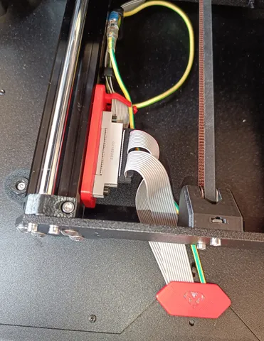
xLCD improved QuickRelease for Original Enclosure and MK4
prusaprinters
This is an alternative Quick Release for the MK4's xLCD in combination with the Original Prusa Enclosure. It is a remix of an idea originally posted in the form by the user @ssmith.When installing an MK4 printer in an Original Prusa Enclosure with the xLCD mounted at the outside of the enclosure, the cable connection is fairly tight and the default configuration requires to unscrew the xLCD every time the printer shall be removed from the enclosure.This quick release adds additional connectors for the display cable and ground connection of the xLCD mounted to the inside of the MK4 printer frame.What to print2x T-slot nuts compatible with the MK4 30x30 frame extrusions (duplicate the one contained in ConnectorMount file)1x Baseplate for additional connector with cable guide (in ConnectorMount file)Requires (organic) supports on the fairly fragile cable guide → See attached PrusaSlicer file as guidance.Use v1a_shortVersion for option 1 2x12 panel mount connector (see below)Use v1b_longVersion for option 2 2x12 panel mount connector (see below)1x CableGuide covering the hole in the enclosure bottom plate (optional)Print this with the flat side down and you won't need any supports.Additionally required parts2x 24-pin Micro-Match Male-on-Wire Connector (Warning: reusing/cutting the original xLCD display cable is not recommended, as the cable length is likely too short)1x 24-pin (2x12) rectangular panel mount connector with flange (option 1, option 2). I used option 1, which is significantly more expensive than option 2, but option 2 seems to be out of stock for a while now.1x 24-pin (2x12) rectangular cable connector1x Strain relieve clip for 24-pin cable connector (optional, but recommended)1x roughly 100cm of ribbon cable with 24 lines and a pitch of 0.05 inch (1.27 mm)I repurposed a cable which I already had. (Reference link, but significantly more than you will need.)You can also use a ribbon cable with more lines and carefully remove the excess of 24 lines, as long as the pitch matches the connectors.While I splitted the 24 line cable in half AFTER attaching the connectors to all ends of the cable (as in the original cable), I would NOT recommend to use two sections of 12 line cables from the beginning, as this might make installing the connectors significantly more difficult.1x rougly 25 cm of ground cable (preferably yellow/green matching the existing cable)1x pair of Quick Connects for the ground cable. I had those, so cannot make an explicit recommendation. It is used as an extension for the original xLCD ground cable, so take that as a reference for size.2x square nuts and M3 screws (should be in your spare parts from the MK4 or enclosure).Installation (might be incomplete)Install the Micro-Match connectors on each end of the flat ribbon cable. Attention: Use the same orientation as used by the original xLCD cable.Follow the original MK4 instruction regarding the installation of the ribbon cable and ground cable on the side of the xBuddy board. Here, use your new ribbon cable but the original ground cable.Also follow the cable management recommendation up to the inner side of the front left frame.Now, you want to cut the new ribbon cable so that you have enough wiggle room to install the 2x12 flanged connector to the frame. When installing the 2x12 connectors to the cut ends of the ribbon cable, make sure that the lines are connected as in the original. Mixing this up may damage the xLCD.Mount the 2x12 connector to the inside of the frame byfirst inserting the two printed T-nuts into the groove of the printer frame and rotating it by 90 degreesadd the M3 square nuts in the slots of the printed T-nutspush the T-nuts into position so that you can add the printed baseplateuse M3 screws to fasten the 2x12 connector with flanges to the T-nutsCrimp the Quick Connects to the new ground cable extensionInstall the front end of the ribbon cable and ground cable through the enclosure opening and connect the xLCD as usual.DisclaimerI did this modification a while ago, so especially the installation instructions are a vague recollection of what I did a few months ago. Feel free to share your experience/feedback and I am happy to update the instructions accordingly.The cable guide at the baseplate is fairly fragile, so be careful when removing the support material.
With this file you will be able to print xLCD improved QuickRelease for Original Enclosure and MK4 with your 3D printer. Click on the button and save the file on your computer to work, edit or customize your design. You can also find more 3D designs for printers on xLCD improved QuickRelease for Original Enclosure and MK4.
