Xinkebot Orca 3 Lead Screws + Dual Z Convertion
prusaprinters
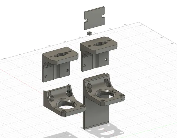
Introduction:Some time ago I made a terrible mistake and bought an Orca 3 IDEX 3d printer from not much known brand Xinkebot. On paper it had pretty nice specifications, and looked as interesting and well thought design. Which indeed was true in that case.What killed that product though, was TERRIBLE quality of assembly, total lack of quality control, and overall awful craftsmanship of factory. Also few design choices revealed to be just bad and lacking long-term testing if they are reliable enough.Result was that my machine suffered from couple of major hardware failures after mere 20-25 hours of work. Over recent year I addressed majority of its flaws, tested invented solutions, and now can share them to everyone who was unlucky to get those machines. Solution2:Z axis in Orca 3 is supported and guided by 2 pieces of ball screws, 1204. 12mm of diameter and 4mm pitch (nut travels 4mm per one full rotation of the screw). They are rotated by single Nema17 motor, with GT2 6mm belt attached to the top of the frame which transfers motion to the second screw. Also keeping them in plus minus sync.Issue is - legit and high quality ball screws are very expensive due to the amount of work and precision required to make them correctly. To keep costs low, Chinese ball screws are made with “rolling drums” method, which is simpler and faster, but results in usually very deformed (bent) screws due to the huge forces acting on the metal during their production. Not otherwise was with Orca 3 1204 ball screws. One of them was bent so much, that it result in huge Z wobble effect on the prints. Usually - when someone is going to utilize those cheap ball screws, he also incorporate come kind of decoupler to compensate wobble of the screw to not transfer those movements into the 3d printer frame. Xinkebot solution does not include such kind of compensating device. Ball screw nuts are in fact “loosely” attached to the X gantry, with screws and springs to allow it some movement, but in fact it works utterly poorly, or do not works at all. Also upper belt solution have its flaws. To move both sides of the X gantry in sync, belt need to be tensed pretty tight, which puts even more bending forces on the screws and whole assembly.To get rid of major Z-wobble, I decided to convert Z axis into classic lead screws, adding so called Oldham coupler to mitigate lead screws axial movements, and also add second Z motor for better weight support and get rid of overly tight Z sync belt on the top. Required hardware:2 x 48mm height Nema17 stepper motors, 1.8 degree. I used LDO-42STH48-2004AC. Though my stepper drivers were switched to TMC5160, if You are still using original Orca TMC2209, You might need to find less power hungry motors with same dimensions. You can also just use smaller motors.2 x T8x4 lead screws, cut to 63cm of length.2 x T8x4 brass nuts. You may also use POM ones.2 x Oldham coupler. I used ones from V-Core3.1 project. They utilize brass parts sliding through POM joint, which is much smoother operation than just brass alone.2 x Z-Stepper cables, around 20 and 50cm lengthVarious M3 and M4 shorter screws hardware.2 x 5x8mm stiff motor shaft coupler (You may reuse one from Orca and buy second one) Print settings:0.2 layer, 4 perimeters, 20% grid infill, 6 bottom and 6 top layers. Material: PLA, ABS, ASA. PET also might be sufficient. All parts should be printed in their original positions.Only Z_motor_mount_L require simple supports in one place.You need:1 x Z_motor_mount_L1 x Z_motor_mount_L_bracket1 x Z_motor_mount_R1 x Z_gantry_L1 x Z_gantry_R4 x M6_to_M4_spacer2 x Z_top_spacer Installation:Turn on the machine and move Z axis that you can put some item under X gantry which will hold it in place and not cause it to fall when you detach ball screws. Turn it off, disconnect power cord.First You need to dissemble old Z solution. Start with removing M4 screws holding nuts to the X gantry brackets. Those ones with little springs of unknown purpose. Once ball screw nuts will be freed, unscrew L shaped brackets they were attached into. There are 4 M3 screws on each side holding it to gantry. Put them aside, they will be needed later.Then move to the top of the printer frame. On middle of the horizontal slab of aluminum there is a belt tensioner - loose it as much so You could slip the belt off its guiding rollers and let it hang loose. Then move to the toothed pulleys attached to the tops of each ball screw. Loose their grub screws so they could spin freely. Move down to the Z stepper motor and loose its coupler. Then move up again and start to unscrew plastic tops. Be careful, under plastic part there is a thin metal spacer which will like to fall out making a lot of noise. Having Z top free, turn it around and pull upward, till it slip off from the ball screw. Do same on the other side. Both 1204 balls screws should be free to be pulled out. Do not let their nuts slide out from the thread, its bearings will fall out, making a lot of mess. Now You can detach Z motor bracket and another plastic holder on another pillar of the frame.(Optional) Having whole X gantry free for moving up and down now, You can use that opportunity to properly set POM wheels on both sides of it. They should be pressed to the pillars without loose, but allowing smooth movement through whole height of the frame.Take Z_motor_mount_L and put it into cut out place of the left pillar of the printer. It is designed to fill and fit the place, although due to poor machining of the pillars there might be required a little sandpapering of the plastic part to perfectly fit into spot. Be careful to not crush filament sensor cable which is going through the extrusion. Screw Z_motor_mount_L to the place using old M5 screws and then slide the new stepper motor under it. Stepper should be flush with the flat part of the mount, touching it. Then slide Z_motor_mount_L bracket into the place and screw the motor to the mount using 6 or 8mm M3 screws. As now the stepper motor is moved a little toward back of the machine, original 6 pin plug protruding from the PCB might not be aligned with the motor socket. Or forcing it to fit might cause it to bend and damage. Better mount the stepper motor with its socket turned toward rear of the machine, and use short 20 cm cable to plug it into the daughter board right under the left pillar. Daughter board underneath, into which is plugged large 40 pin ribbon cable, have not used sockets which are wired to the motherboard. They are signed, so just locate one described as M_Z and plug the cable there. There is enough space to thread the cable through rift above to reach the stepper motor, just like on the second photo.Having that part done, move to the other side of the machine. Take Z_motor_mount_R and screw new stepper motor to it. For now loosely, to make it flush with the pillar. Then attach this setup to the pillar using M5 screws. You will need to plug additional stepper to the motherboard, but leave it for later for now.Attach couplers to the Z stepper motor shafts, and then move to the top of the frame. From original plastic Z tops, You will need to remove upper bearing, and turn upside down lower one, that it do not fall down when part will be installed. Install them back to the pillars, do not using original metal spacers, but freshly printed Z_top_spacer. They are a little thicker to ensure new lead screws will be aligned with the motors below. Now with a bit of fiddling, take new 63cm T8x4 lead screw and slide it from above through the plastic Z top, pulley, bearing, and all way down to the motor coupler. Do not screw it yet, let it being able to slide up and down when needed. Do the same to the opposite side.Now take two Z_gantry printed parts and attach Oldham couplers to it, using short M3 screws. Cylinder head or flat head, it have no matter, there is enough space in the hole above to hide and do not protrude. Now take them, lift lead screw up a little and slide them through the hole to the level of X gantry. Take original metal L brackets and put them on plastic parts in original palce of their assembly to the gantry. You will need a tad longer M3 screws than old ones to attach it in all four points. Check last photo as the reference. Make sure that lead screw goes as close to the center of the hole as possible. There might happen, that metal L bracket will catch against the X motor, making moving it to the desired position impossible. In such case, just grind a little side of the metal part, so it could be aligned properly. Once it being in place, put M6_to_M4_spacers into holes of the L bracket, and use 2 M4 screws to bind it with plastic part below. It should be rock solid now.Take brass (or POM) nut and lift lead screw up once again to thread it on it, then moving it all way up till it touch underside of Oldham coupler. Screw nut to the coupler using 2 M3 8mm screws. Now - even if Your lead screws are slightly bent and wobble during rotation, Oldham coupler will compensate that motions do not affecting height of the X gantry.Now move again to the top of the frame and put GT2 belt into its guiding bearings, and set the tensioner. As now it is not transferring any significant forces, only acting as sync belt, You do not need to set it overly tight. Watch the lead screws when You will set the tensioner, if they start to bend, it means there is too much tension on the belt.Make sure Your X gantry is perfectly leveled on both sides, use pieces of equal height blocks or similar objects to make it rest on them. When it is leveled, secure toothed pulleys with their grub screws. Almost everything is done.There persist only plugging second Z motor to the motherboard. Orca 3 motherboard is in fact just a customized BTT SKR Pro 1.2 (it have added ports for ribbon cables), and above Z stepper driver there are already 2 ports present to plug stepper motors in parallel. Flop the printer on the side, and then remove acrylic cover of the mother board. Z ports are signed, one of them have 2 jumpers on it. Theoretically, if Z_1 port is doubled (on the daughterboard under left pillar of the machine), and even tripled (original palce where Z motor was plugged), then Z_2 port is free and can be utilized to power our second Z motor. Just remove the jumpers and plug long enough cable to it to reach second motor. Unfortunately, from some reason it didn't work for me and second motor started to act when was plugged straight to the Z_2 port. But, as that whole circuitry of the machine for the Z works like a giant Y splitter, You can just plug second motor into Z_1 port, and it will work as well. Plug it there, and make sure You do not attached lead screws to the motors shafts yet. You need to check if they rotate in same direction.Turn machine on and navigate to the Movement section, set 10mm distance and touch Z up or Z down button. Both motors should move into same direction. If Your new motor is turning opposite way, or is shaking or clicking instead of rotating, then You need to modify wiring of the second motor cable. If its turns opposite direction, just set the cables in the JST plug in the opposite order. If it clicks and shakes, then switch places of the middle pair in the plug.When both motors turn in same direction, then You can finally screw lead screws to the couplers, binding them with motors. As the new T8x4 lead screws have same pitch as the old 1204 ball screws, no additional tuning is required. Though as You have now two motors to power with single stepper driver, You might now need to slightly boost its power output, depending on motors and stepper Your setup have. You can set it in printer menu, going into Machine→Settings→Current. Default is 800mAh, for TMC2209 You can boost it up to 900. Just do not overdue it, even if You have two motors now, each of them need to do only half of the job which old, single one needed to make lifting whole gantry alone. Its good to check if during some test print they do not start to overheat. They might be warm, its normal, just not hot. If they become, then lower the current.
With this file you will be able to print Xinkebot Orca 3 Lead Screws + Dual Z Convertion with your 3D printer. Click on the button and save the file on your computer to work, edit or customize your design. You can also find more 3D designs for printers on Xinkebot Orca 3 Lead Screws + Dual Z Convertion.