X5SA PRO Bondtech Direct Drive V6 with BLTouch Mount
prusaprinters
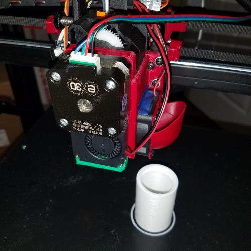
<p>Updated Jan. 3rd, 2022</p> <p>-Updates in their own section-</p> <p>The X5SA is my first experience with a Bowden extrusion setup. I found I kept using my A8 even though I know the TRONXY is a (potentially) superior machine. The responsiveness of a direct drive is what I've come to expect. There seems to be a new generation of extruders that are overcoming this hurdle but I don't have any of these in my possession yet. I understand the intrinsic relationship of lightweight equipment with fast printing speeds, but given the tech level of my parts bin, and that generally, I don't run faster than 60mm/sec, I think the additional weight will be an acceptable tradeoff.</p> <p>This was designed to reuse as many of the stock parts as possible. Parts you will need include:</p> <p>Bondtech extruder</p> <p>Pancake motor</p> <p>V6 hotend</p> <p>BLTouch sensor</p> <p>Assorted hardware</p> <p>Hardware BOM is included in its own section further towards the end.</p> <hr/> <p>The front housing is designed to print flat on its front face so you'll need to print one (possibly two depending on the fan design) "4010 MOUNT"(s) to give the part cooling fan the proper spacing.</p> <p>Please note, the extruder cooling fan is mounted in reverse. That is, its exhaust is flowing in a positive X direction. This is an attempt to negate any unwanted part cooling resulting from pressurized air escaping from the cracks in the housing.There will need to be a part to redirect the exhaust flow. There are several designs out there. The one I chose is listed below.</p> <p>In the renders, the "FRONT HOUSING" is colored red, the "REAR PLATE" is colored blue, and the "4010 MOUNT" is yellow. The 4010 mount is hard to see as the fan model I used has slightly thicker mounting ears than the fan I received from TRONXY so they merge together visually.</p> <h3>Print Settings</h3> <p><strong>Printer Brand:</strong></p> <p>Anet</p> <p><strong>Printer:</strong></p> <p>A8</p> <p><strong>Rafts:</strong></p> <p>No</p> <p><strong>Supports:</strong></p> <p>Yes</p> <p><strong>Resolution:</strong></p> <p>Adaptive; 0.1-0.3mm</p> <p><strong>Infill:</strong></p> <p>15% gyroid</p> <p><strong>Filament:</strong> Smartbuy ABS</p> <p>Red</p> <p><strong>Notes:</strong></p> <p>0.4mm nozzle, 240c hotend, 110c bed, seven perimeters, four top and bottom layers, 24mm/sec speed throughout. Used a 25 loop skirt to minimize warping.</p> <p>Probe offset:</p> <p>X: -29.625mm</p> <p>Y: -6.3mm</p> <h3>How I Designed This</h3> <p><strong>Credits and Hi-resolution gallery</strong></p> <p>I was inspired heavily by this thing's design:</p> <p><a href="https://www.thingiverse.com/thing:4610797">https://www.thingiverse.com/thing:4610797</a></p> <p>I modified the thing in here:</p> <p><a href="https://www.thingiverse.com/thing:3956504">https://www.thingiverse.com/thing:3956504</a></p> <p>to get the overall shape of the Y axis endstop switch plate. I actually use the other pieces too.</p> <p>The cooling fan duct was adapted from this design:</p> <p><a href="https://www.thingiverse.com/thing:4075204">https://www.thingiverse.com/thing:4075204</a></p> <p>I reused the mounting section and lofted some new air passages. Print with the 45-degree angle flat on the bed for a support-free print.</p> <p>The 40mm heatsink fan duct is this one:</p> <p><a href="https://www.thingiverse.com/thing:4761959">https://www.thingiverse.com/thing:4761959</a></p> <p>Also, print at a 45-degree angle for a clean supportless print. I sink the model down below the print surface a tad in the slicer to give a bigger footprint for added stability. Then I included a five perimeter, three-layer high skirt to keep it attached.</p> <p><strong>Left to right: PETG White, PLA Natural, Ninjaflex Black. Untuned profiles.</strong></p> <p><strong>Left to right: PETG White, PLA Natural, Ninjaflex Black. Untuned profiles.</strong></p> <p><strong>Left to right: PLA Natural, Ninjaflex Black. Untuned profiles.</strong></p> <p><strong>Left to right: PETG White, PLA Natural, Ninjaflex Black. Untuned profiles.</strong></p> <p><strong>Left to right: PETG White, PLA Natural. Untuned profiles.</strong></p> <p><strong>PETG Khaki. Untuned profile.</strong></p> <p><strong>PETG Khaki. Untuned profile.</strong></p> <p><strong>PETG Khaki. Untuned profile.</strong></p> <p><strong>PETG Khaki. Untuned profile.</strong></p> <p><strong>PETG Khaki. Untuned profile.</strong></p> <p><strong>1d 14hr 41min.</strong></p> <p><strong>Finally a successful print.</strong></p> <p><strong>Photopolymer resin version, printed on a Voxelab Proxima @ 0.05mm layer height.</strong></p> <p><strong>Heat damage and residue.</strong></p> <p><strong>Lots of foreign material in the heatsink housing.</strong></p> <h3>Assembly Guide</h3> <p><strong>Hardware BOM</strong></p> <p>Rear Plate-</p> <p>M3x8 (x2)</p> <p>M3x10 (x2)</p> <p>M3 Flat Washer (x2)</p> <p>M3 Hex Nut (x6)</p> <p>Extruder Motor to Extruder-</p> <p>M3x40 Socket Head (x3)</p> <p>Front Housing-</p> <p>M3x10 (x6)</p> <p>M3 Flat Washer (x5)</p> <p>Extruder Fan-</p> <p>M3x16 (x4)</p> <p>M3 Flat Washers (x4)</p> <p>Part Cooling Fan-</p> <p>M2x12 Sheet Metal Screws (x4)</p> <p>BLTouch-</p> <p>Provided hardware</p> <p>X-Axis Endstop Switch-</p> <p>M3x5 (x1)</p> <p><strong>Assembly steps</strong></p> <p><strong>STEP 1: BACK PLATE</strong>Hardware needed:</p> <p>M3x8 (x2) M3x10 (x2) M3 Flat Washer (x2) M3 Hex Nut (x6)</p> <p>Insert all the M3 Hex Nuts into their respective spots on the rear of the plate:</p> <p>Next, due to more spatial constraints, you need to make two of these out of the two M3x10 screws and two of the hex nuts:</p> <p>Then get those assemblies and the M3x8 screws and M3 washers in place<em>as shown</em>:</p> <p>Be keenly aware of which are 8mm long with washers and 10mm long with hex nuts or the front housing will not sit flat.</p> <p>**STEP 2: FRONT HOUSING WITH LEVEL SENSOR, AND EXTRUDER</p> <p>Hardware needed:</p> <p>BL/3DTouch-</p> <p>Provided hardware</p> <p>Extruder Motor to Extruder-</p> <p>M3x40 Socket Head (x3)</p> <p>Front Housing-</p> <p>M3x10 (x5) M3 Flat Washer (x3)</p> <p>Start by partially securing the level sensor as shown; it will be easier to attach later this way:</p> <p>Slide the extruder/heatsink assembly in as shown with attention given to the way the print fits between the heat sink fins:</p> <p>Make sure your heat block is aligned like this:</p> <p>Tighten down the three M3x40mm socket head screws while making sure the faces of the housing, motor, and extruder are all flat to each other:</p> <p>With three M3x10 screws and three washers, attach the left side of front housing to the rear place:</p> <p>You need to wiggle the sensor out of the way to get at the one lower screw.</p> <p>Attach the right side of the housing with the last three M3x10 screws with no washer on the screw in the recessed hole (forgot this picture. Use the holes as shown in this pic from the rear):</p> <p>Then finish installing the bed level sensor:</p> <p>**STEP 3: EXTRUDER FAN, PART COOLING FAN, AND X-AXIS ENDSTOP SWITCH</p> <p>Hardware needed:</p> <p>Extruder Fan-</p> <p>M3x16 (x4) M3 Flat Washers (x4)</p> <p>Part Cooling Fan-</p> <p>M2x12 Sheet Metal Screws (x4)</p> <p>X-Axis Endstop Switch-</p> <p>M3x5 (x1)</p> <p>Attach the extruder fan with the four M3x16 screws with washers as shown (make sure fan's exhaust direction is correct/reversed):</p> <p>Mount the part cooling fan with the fan duct using the M2x12mm sheet metal screws. Do not overtorque:</p> <p>Use the M3x5mm screw to hold down the X-axis endstop switch with the edge of the circuit board resting against the protruding boss on the housing (mine is broken off, hard to see):</p> <p>After this, it's a matter of plugging everything back in and test running the new setup.</p> <p>The heat block should be oriented so the heater cartridge and temp sensor will come from the right. There is a space and ridge that the wiring rides behind the bed level sensor:******** Updates =======</p> <p><strong>- Newest to oldest -</strong></p> <p>Jan. 3rd, 2022:</p> <p>The printer has been logging considerable printing time since the last update and has been performing admirably. I decided to do a tear-down and inspection while gathering the last info and pics to wrap this thing up.</p> <p>The only update to the model was a cutaway on the underside of the rear plate and front housing where they make contact with the heat block when removal is attempted without further disassembly of the hotend. I have not actually tested the new model as I managed to get the block off with only a little marring of my existing print, so I didn't need a new one. YMMV.</p> <p>Upon separating the plate from the housing, I was greeted with a lot of filament powder inside. It seems the extruder fan pulls a lot of air through the cracks. The was some heat damage but I was expecting more. You can see the abuse (and some of the residual powder) in the pictures used in the assembly guide part later. No heat shielding was used for testing purposes, but I would highly recommend it.</p> <p>Other than that, the pieces were fine.</p> <p>The formatting of this Thing's page has been worked over.</p> <p>The Hardware BOM has been updated.</p> <p>Included is an assembly guide as the process has its tricky moments.</p> <p>Also, I consider this Thing to be done; work-in-progress status removed.</p> <p>If you make one, please post it!</p> <hr/> <p>June 6th, 2021:</p> <p>Posted some pictures of the calibration cubes and other stuff covered below in the high-res gallery section.</p> <p>The printer has been working non-stop since reassembly and everything has been clicking along the tracks nicely. Currently it's grinding out a <a href="https://www.thingiverse.com/thing:4176380">Designer Lithophane Moon Lamp by humphrey_b52</a>, which is one of the pics added to the gallery. A long print to be sure. I included the time elapsed display for dramatic effect.</p> <p>I also included in the picture is the spool holder I am using, the <a href="https://www.thingiverse.com/thing:4444805">Bear Spool Holder Remix by Buckztheman</a> but it was printed at a shorter height to accommodate the hardware pinned to the middle of the printer's frame. I will eventually remix it a bit and it will serve as a guide for filament fed from below and behind the printer out of a dry box.</p> <p>Some build notes:</p> <p>For some reason it took four or five attempts to successfully reprint the modified part cooling fan duct. The first one in green PETG was a home run the first attempt. Not so much the second time with transparent red PETG. I think the filament was a bit hydrated because success occurred the second print attempt after drying the roll overnight. A pic of the orientation I use has been included.</p> <p>Although the PETG version did eventually print well, and it is what I'm using on the TRONXY, I was getting quite frustrated and was simultaneously setting up a supported model for resin printing. Strangely both the resin and the final PETG print ended at about the same time. A pic of the resin piece was posted as well. For those that want to print a resin part I've include the supported model for convenience. The supports are messy but it worked first try. Perhaps you can see my fluster built into the support structure :)</p> <p>I did have the previous version of this design running pretty rigorously and it seemed to show some wear and tear. Pictures, again, have been posted in the gallery. The underside of the mount just above the heat block took some damage for sure. Maybe a little heat shielding would do some good.</p> <p>What I found interesting is the heat deformations increased the gap between the front housing and the rear plate, allowing a lot of particulates and other material to get sucked up into the heat sink area. It seemed to be sucking things up between the other gaps as well. There is only a relatively small size opening that the fan is pulling through. I might consider enlarging that on the next go around here.</p> <p>In general, I'm super pleased on how things turned out. Very few things need to be checked off before this design is finalized, but as it stands it's a fully-fledged unit.</p> <hr/> <p>June 4th, 2021:</p> <p>Short update: It prints great. I got everything reassembled and did some calibration cubes. I will post more when I get home tonight but I just wanted to say everything works well together, for those who are interested.</p> <hr/> <p>May 31st, 2021:</p> <p>It is a holiday here in The States, and this project is making me late for the festivities, but what's done had to be done. No time for verbosity this time, just some new files that I feel may indeed be The Ones. Well, they are at least within a couple of revisions away from perfection. The first print is on the bed so everything has been untested.</p> <p>The front, rear, and fan duct models have been updated. You may need two 4010 mounts now as well.</p> <p>Caveat emptor.</p> <p><em>Updated update:</em></p> <p>The mounting boss for the X-axis endstop was shortened.</p> <p>Extensions were made to the bottom of the front housing to accommodate a bottom pair of mounting points for the cooling fan.</p> <p>The duct for the cooling fan actually works okay but the twisted air passage was rubbing on the housing so it was relofted to make it interference-free.</p> <p>The circular opening to the extruder heatsink fan was reduced by about a millimeter to eliminate the gap between the fan and housing in my setup.</p> <p>There was a filet added to the front housing to reduce the weakeness along the one mounting tab as well because I broke two prints in the same place trying to remove the supports.</p> <hr/> <p>May 10th, 2021:</p> <p>While trying to print a Benchy in PETG I was forced to get to work on the fan duct. It has been uploaded and does seem to work okay. I wanted to put it through some flow testing but that has to wait. I use small M2 screws to pin the ears together and the whole duct just hangs off the fan. I will add some bosses or holes or something so the assembly will have attachment points at the bottom. It's just too floppy and weird in its current state.</p> <p>Also, the fan hangs very very low and will catch on those occasional curly bits that stick up above the printing plane. It seems to be a feature I will have to change.</p> <p>A video has been uploaded and you can see what the current setup is doing. It has problems pulling the filament through all the teflon tubing. All the resistance is making for inconsistent extrusion.</p> <p>Previously I had printed a 20mm calibration cube and it was suffering from those tell-tale aberrations spaced exactly 8mm apart. I undid the top bearings of the threaded rods and it seemed to have helped with most of the Z-banding. I might go back to the original all-metal spring-type shaft couplers as they have more flex and more forgiveness built into them I believe. More testing and printing has to be done, however, to work out all those little kinks that arise over time.</p> <p>So far not so bad.</p> <hr/> <p>May 4th, 2021:</p> <p>I finally got time to move this project forward. For the record, I'm still not moved in completely but I got a job running 3D printers, so I go that going for me. With the new job as a driving force I finally got this to a working prototype.</p> <p>I solved the gap with the smooth rods by making some <a href="https://www.thingiverse.com/thing:4849553">Z-rod compensator brackets.</a> They seem to do the job ok.</p> <p>Included is a video of the printer making a 20mm calibration cube. The whole thing does "work" but it still has some adjustments to be done.</p> <p>Not all the mounting holes for the rear line up yet but I got a couple in just to hold it on.</p> <p>There is still a gap around the perimeter of the extruder fan. Blue tape has come to the rescue for testing purposes.</p> <p>The mount for the X-axis min switch is a bit loose and the screw doesn't seem to want to stay threaded in. I haven't looked at the clearances but I dream of putting a captured hex nut in for extra security. The mounting post is also too long and the switch button barely misses the X-gantry plate and fails to trigger. That is the reason for the binder clip in the video.</p> <p>The extruder fan does a fantastic job of creating a chaotic exhaust flow that goes everywhere. I printed out a <a href="https://www.thingiverse.com/thing:4761959">40mm Fan Duct with 90 Degree Deflector by max-e-moose</a> that I believe will work to direct the airflow upwards but I have not yet installed it.</p> <p>I have also yet to endeavor the creation of a useable cooling fan duct.</p> <hr/> <p>April 11th, 2021:</p> <p>Still very busy. To make excuses, I'm in the middle of an employment change as well as still moving into a new place. That is secondary as other issues are slowing down the finalizing of this thing. After many goes at squaring the printer, I found the smooth rods for the Z axis are short and bend/pull in the top, bottom, or depending, possibly both of the 2020 extrusions. This explains many things. Apparently, this has been an issue with the printer, as evident here: <a href="https://www.thingiverse.com/thing:4808796">TronXY X5SA 500 Lower Z Smooth Rod Stabilizer by AutoWiz</a></p> <p>I've got to nail down a way to shim or correct the gap, preferably with a non-3D printed solution using a material with very low creep. I bought a 3018 CNC machine with the goal of producing just this kind of thing out of 6000-series aluminum but I realize that is a ways off for the current setup after a few initial runs with it. As it stands, however, it is hard to trust the square of the design without a calibrated system to measure it.</p> <p>Things are moving forward though and progress will return to normal as things settle down with my life situation.</p> <hr/> <p>April 2nd, 2021:</p> <p>I have been very busy and have not had much time for development but this project has not been forgotten. I checked the alignment of the holes and they look good, and that's as far as I got.</p> <hr/> <p>March 28th, 2021:</p> <p>I decided to not go with a shim to fill the motor to extruder gap and just make the housing thicker for better integrity.</p> <p>I realigned most of the rear plate mounting holes.</p> <p>The revised parts are printing now, should have results later today. The model files have been uploaded nonetheless.</p> <hr/> <p>March 27th, 2021:</p> <p>The rear plate sits flat now although I realized the lower left hole for the mounting screw is not lined up very well and it feels unhappy when I put in a screw. I'll have to realign that for peace of mind.</p> <p>Thankfully the belt clearance/alignment issue has also been resolved. The hole for the recessed nut was not a problem after all. It sits very securely in its pocket.</p> <p>I filled in the holes around the extruder fan area in the models although it was late late late at night and it kind of turned into a hot mess. Due to the way I've made the design clamshell-ish I found one of the hole filler areas on the rear plate was going to be very hard to print. I decided to try to add more material around it to keep it from having cooling issues and that's where it got away from me. It looks serviceable but it's not a tidy add-on at all. The front housing additions look to be fine.</p> <p>I also noticed that the M3x40mm screws bottom out in the extruder motor leaving a slight gap between it and the housing. I have to add 1-2mm of material there to fill that space. Perhaps a shim?</p> <hr/> <p>March 26th, 2021:</p> <p>I finished the Y endstop switch mount today. I tried to mount a heatsink that I have on the extruder motor but it contacts the frame before the switch is triggered. There are a couple of millimeters more room before the nozzle moves over the bed's airspace; I could scoot the switch forward some more but I don't think I'll be needing a heat sink.</p> <p>A couple of adjustments were done to the rear plate as well. A closer inspection of the mounted setup revealed the rear plate was curling away from the metal gantry plate. It gave everything an angle a few degrees out of vertical alignment. At first, I thought it was classic ABS warpage but after I took the plate off and removed the hardware it was flat and level. Some of the holes are still too small and some screws had to be forcefully screwed in. I thought maybe that could be the cause of the deformation. I opened up all the holes in the rear plate just to see, plus, I hated having to screw in the majority of them anyways.</p> <p>The plate was also interfering with the belts and how they sat on the gantry hook. The plate's top edge stuck up too far and pushed the belt position upwards, causing the belt to grind on the nearest idler pulley from the bad alignment. I increased the depth of the cutout to give more room for the belt. I hope that works because I think with any more removal and the pocket for the closest recessed nut won't work so well.</p> <p>I'm considering adding captured nuts to the extruder cooling fan mount. The ABS is so soft and I'm suspicious of how well it will do with holding on to those screw threads. This is not on the official to-do list though.</p> <p>I also didn't consider that with the extruder cooling fan mounted in reverse it no longer has a nice square frame flush with the housing. There are a lot of gaps around the contours of the fan to let air in. That flaw will definitely have to be addressed.</p> Category: 3D Printer Parts
With this file you will be able to print X5SA PRO Bondtech Direct Drive V6 with BLTouch Mount with your 3D printer. Click on the button and save the file on your computer to work, edit or customize your design. You can also find more 3D designs for printers on X5SA PRO Bondtech Direct Drive V6 with BLTouch Mount.