X2 BL Touch Mount
prusaprinters
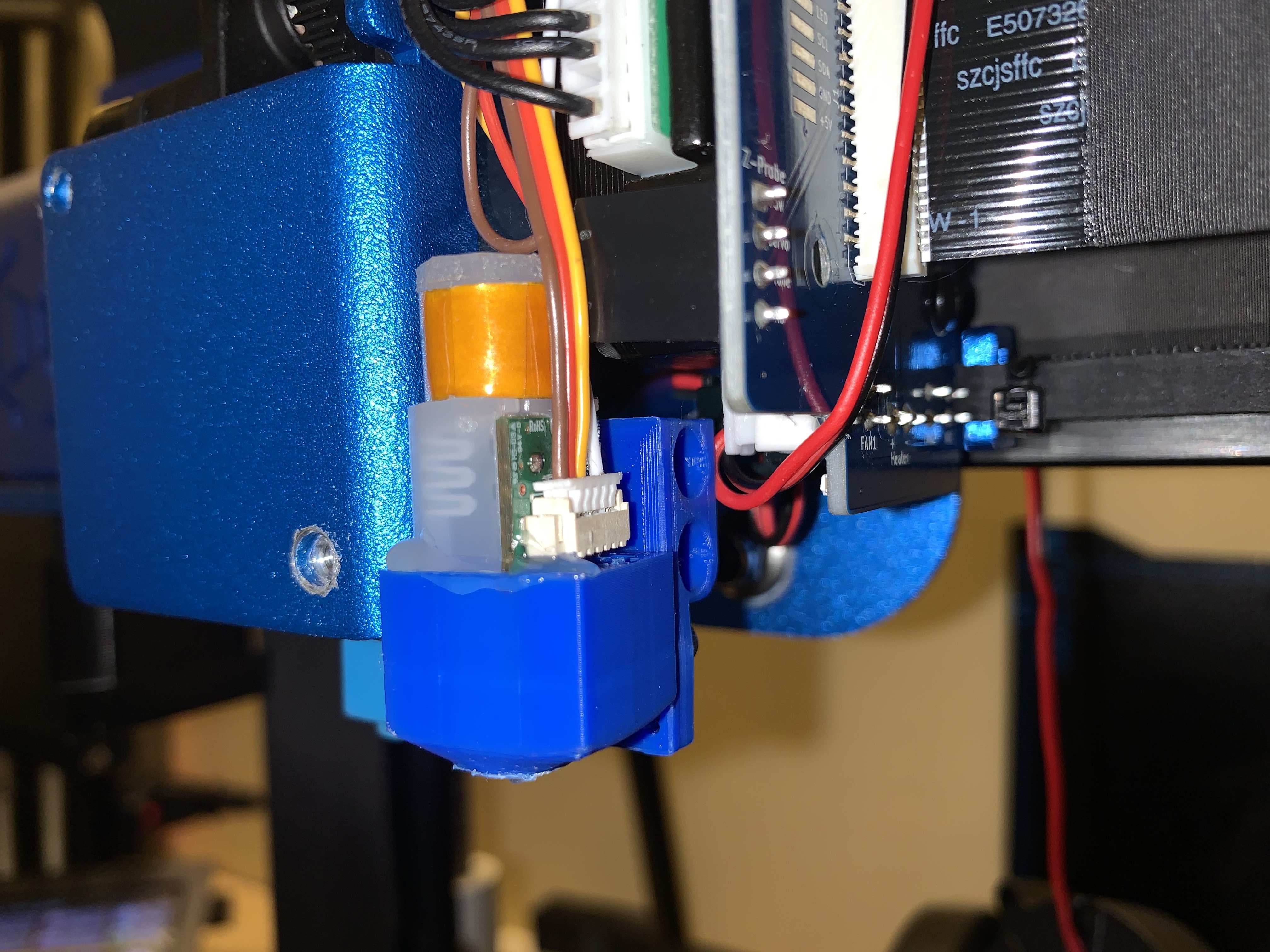
<h3><strong>BLTouch (v3.1) install on a Sidewinder X2</strong></h3><p>There isn’t a lot of published information on whether or not this will work. I’m accustomed to doing things both wrong and the hard way, so after the probe broke on my X2 I decided it was time to upgrade.</p><p>The stock probing system on the X2 isn’t bad, but it’s also not great. Even after having it dialed in, it would randomly require change in Z height on the first layer every so often. After breaking the probe during a failed print, I replaced it with a new BL Touch. Any of the BL Touch models I’ve seen so far have all been external to the enclosed print head. I wanted it to be inside to retain the clean appearance of the printer.</p><p>Assuming you’re using my models to mount the probe, print them according to these settings:</p><h4><strong>Print Setup:</strong></h4><ul><li>Printed on an Ender 3 Pro</li><li>Supports: Tree (everywhere will work since there are no hollow parts)</li><li>Infill: 99%</li><li>Extrusion Width: 0.3 (this will give you two layers on the thin walls instead of one)</li><li>Wall line count: 4</li><li>PLA at 200º (or PETG at the necessary temp)</li><li>Bed temp of 67º (glass bed with no adhesion aids)</li><li>50mm/s</li><li>20mm/s initial layer</li><li>.12mm layer height</li><li>Orientation<ul><li>Print the probe housing vertically (round hole side down)</li><li>Print the mount lying flat (largest flat side down)</li></ul></li></ul><p>The first thing that must be done is remove the stock probe by loosening the two mounting screws. Put one (or two if you’re able) M2 nuts in the retaining slot of the probe holder. Place the mounting part (the part with the two holes in it) into position and use the stock screws to secure it in place. Leave it as loose as possible to help with the next steps.</p><figure class="image image_resized" style="width:50%;"><img src="https://media.printables.com/media/prints/282376/rich_content/8353453b-284b-466e-bfc0-5f798837022a/picture4.png#%7B%22uuid%22%3A%226cd1617e-154a-4901-8515-dddb770a8815%22%2C%22w%22%3A880%2C%22h%22%3A660%7D"></figure><p> </p><p>Take small, sharp, wire cutters (like the ones that are shipped with printers) and cut off the mounting ears and round the top of the BL Touch probe. Don’t cut inside of the small circle of plastic because there is a copper coil inside.</p><figure class="image"><img src="https://media.printables.com/media/prints/282376/rich_content/a2704fca-86da-46c6-a8e7-e251fea8a52e/image.png#%7B%22uuid%22%3A%220dd44a15-6a6a-4c60-928d-ff4be998f521%22%2C%22w%22%3A220%2C%22h%22%3A218%7D"></figure><p> </p><p>Place one (or two) M2x10 bolts through the slot in the mount and into the slot of the holder. Begin but do not tighten the bolt so that you can adjust it after installation.</p><figure class="image"><img src="https://media.printables.com/media/prints/282376/rich_content/a651700a-3fa1-4e8b-a31b-420e71429bea/image.png#%7B%22uuid%22%3A%22e4efa6d9-3732-46cb-bdae-1fc02fd6d845%22%2C%22w%22%3A242%2C%22h%22%3A322%7D"></figure><p> </p><p>The BL Touch requires about a 4mm clearance from the bed in order to work. I’ve installed several of these probes and I find it best to start by getting the nozzle to touch the bed. Then use a 4mm hex wrench and place it under the probe tip (retracted). Allow it to rest there while you tighten the M2 bolt. It won’t take much to break the mount so just get it reasonably tight. I have revised the probe holder quite a few times so that it should fit nicely. Because of this however, I’d recommend a small amount of hot glue be used to keep it from moving.</p><figure class="image"><img src="https://media.printables.com/media/prints/282376/rich_content/ebb0b995-cd09-494f-ad5d-953c734689fc/image.png#%7B%22uuid%22%3A%22de93e631-fb57-49a2-95f8-34a86b8a4b61%22%2C%22w%22%3A470%2C%22h%22%3A332%7D"></figure><p> </p><p>Now, in order to get the wiring harness to work we will have to do some modifications. Take the pins out of the end of the connector and replace them into a basic 1x4P Dupont connector in this order. When you install this on the print head PCB, the orange wire will be on top (X2 only, I haven’t confirmed this on other printers). You’ll notice the probe has two ground wires. One is used for the probe on Z height, the other is used for the bed leveling part of the probe. Using a single ground has worked fine for my install. I de-pinned the black end-stop probe wire and used only the brown wire seen here. </p><p> </p><figure class="image image-style-align-right image_resized" style="width:50%;"><img src="https://media.printables.com/media/prints/282376/rich_content/b995b1b0-63fd-4c29-8f3e-fce393be4fe5/image.png#%7B%22uuid%22%3A%2278d35e55-ca08-40f8-8784-a6e1ec5cb33c%22%2C%22w%22%3A480%2C%22h%22%3A196%7D"></figure><p> Orange: 5VDC</p><p> Yellow: Servo</p><p> White: Probe </p><p> Brown: Ground</p><p> </p><p>Now, due to the limited space, you will need to sand off the front and back side of the 4 pin plastic pin holder. It takes very little time or effort to do this with some decent sandpaper. I removed approximately 1mm to get a small space between the probe and the connector. I also removed the white plastic connector base on the PCB since it was not needed any more. Once the connector is installed, I then gently pushed the pins towards the back of the printer (angling away from the top of the probe). This will help keep the wiring from getting chaffed or damaged.</p><p> </p><figure class="image image_resized image-style-align-center" style="width:75%;"><img src="https://media.printables.com/media/prints/282376/rich_content/272b3b03-6362-4aac-8d49-7fb533c94a4e/picture5.png#%7B%22uuid%22%3A%225ba5f66f-4439-4ae0-a887-e338985f25b4%22%2C%22w%22%3A1012%2C%22h%22%3A632%7D"></figure><p> </p><figure class="image image_resized" style="width:50%;"><img src="https://media.printables.com/media/prints/282376/rich_content/14b9c995-fc68-429a-a9cf-6294aa7f2e42/picture2.png#%7B%22uuid%22%3A%229a69763d-7e70-4dda-a09d-3a9599b824fa%22%2C%22w%22%3A1035%2C%22h%22%3A783%7D"></figure><p> </p><p>Once the connector is hooked up, the print head can be put back together. You may notice the plastic beauty cover may not want to fit very easily. It will fit if you work at it. You must be patient and careful when putting that cover back on. I think a later upgrade that includes a better fitting cover for this particular mod may be coming next.</p><p> </p><p>After everything is installed, power on the printer and reset the probe offset to the following:</p><p>X: 21.9</p><p>Y: -12.8</p><p>Z: -3.18 (this is not something I would set as your value will be calculated after leveling)</p><p> </p><p>If wired correctly as soon as you powered on the printer, you should hear the probe go through a self test by releasing and then retracting the probe. Provided this is the case, home all axis. Once the process is complete, move the Z axis down until you get the nozzle to lightly touch the bed. You can use a thin piece of paper but make sure you adjust your final Z offset value by the thickness of the paper used. Here is my process for setting the Z offset</p><ol><li>Move Z axis down as mentioned above until the nozzle contacts the bed very lightly.</li><li>Read what the printer thinks is the current Z height.<ol><li>If you reach 0 and the nozzle is still not touching the bed your Z height isn’t “negative” enough. <ol><li>Increase the value (more negative value) by approximately .1mm (higher if you see that it’s clearly more than .1mm.</li><li>Save the probe value and re-home the Z axis.</li><li>Attempt to do the same thing by moving the Z height towards the bed until the nozzle lightly touches the build plate.</li><li>If it’s still not touching the bed, repeat the first step in this subset and continue to re-home the Z axis.</li><li>A successfully set offset will result in the displayed Z height equal to the probe height from the bed. Approximately 0.1 using a piece of paper, or 0.0 if in contact with the bed.</li></ol></li><li>If you have a positive amount of remaining Z height when the nozzle is in contact with the build plate do the following:<ol><li>Record the value of the Z height.</li><li>Locate the currently stored Z probe offset value.</li><li>Add the recoded value to the negative value shown for the stored Z offset. This should result in a higher (less negative) value. See below:</li></ol></li></ol></li></ol><ul><li>Z axis moved to a point where probe is in contact with the bed.</li><li>Printer displays a Z height of 0.90</li><li>Firmware values for Z probe offset displays -2.91mm</li><li>0.90 + (-2.91) = (-2.01)</li><li>Set Z probe offset to -2.01 and repeat the process.</li><li>At nozzle contact with build plate, displayed Z height should be 0.0</li></ul><ol><li>After the Z probe offset is determined, ensure that value is saved in the firmware.</li><li>To test the values and make final adjustments, print a calibration squares test.<ol><li>In every case I’ve always had to adjust my Z offset slightly.</li><li>To prevent damage to the bed I’d recommend being on the baby step menu as soon as the printer begins the homing process. I usually have the 1mm change selected and I’m ready to press the Up button to keep from marring the bed with the print nozzle. If you see that you’re too high from the bed when the print starts, change it in intervals of either 0.01 or 0.1 (going down) until the material is properly dispersed on the print bed.</li></ol></li></ol><h4><strong>Final Notes</strong></h4><p>With my current setup, I’ve noticed that the 4mm initial probe mounting height is pretty close to the same point of where the probe housing meets up with the bottom of the mount (see below). This isn’t to be used in place of a true measurement but can be used to get a good starting point since assembly can be frustrating with the limited space.</p><figure class="image image_resized" style="width:50%;"><img src="https://media.printables.com/media/prints/282376/rich_content/e314d4b2-8a8e-47ca-9a79-88a47a2cfcaa/picture1.png#%7B%22uuid%22%3A%22a84b7da9-647c-4d85-9c82-52cf16604b9c%22%2C%22w%22%3A1232%2C%22h%22%3A1283%7D"></figure><h4><strong>Parts List:</strong></h4><p>M2 Nut: 1x or 2x as needed.</p><figure class="image image_resized image-style-align-center" style="width:50%;"><img src="https://media.printables.com/media/prints/282376/rich_content/3b5aca27-47fd-4168-8fae-9e0dc0c4ede0/img_1086.jpg#%7B%22uuid%22%3A%2281611f28-a296-4049-a515-7835f5b8766d%22%2C%22w%22%3A1451%2C%22h%22%3A1419%7D"></figure><p>M2x10 Bolt: 1x or 2x as needed.</p><figure class="image image_resized" style="width:50%;"><img src="https://media.printables.com/media/prints/282376/rich_content/39a88e4c-9486-4dfa-8bb3-d59b79d63f62/img_1085.jpg#%7B%22uuid%22%3A%22fb257e4e-dcad-45b5-a20a-136ed7580da8%22%2C%22w%22%3A1347%2C%22h%22%3A1553%7D"></figure><p> </p><p>1x4P Dupont Pin Connector</p><figure class="image image_resized" style="width:50%;"><img src="https://media.printables.com/media/prints/282376/rich_content/0c47aada-ac9a-44e6-98d9-89ef8ccc24e5/img_1087.jpg#%7B%22uuid%22%3A%22742a24b6-af92-4cbd-a02c-085e3c69cfef%22%2C%22w%22%3A1423%2C%22h%22%3A1733%7D"></figure><p> </p><p>Sharp object to extract the pins</p><p>Small amount of hot glue</p><p>Patience</p><p> </p><p> </p>
With this file you will be able to print X2 BL Touch Mount with your 3D printer. Click on the button and save the file on your computer to work, edit or customize your design. You can also find more 3D designs for printers on X2 BL Touch Mount.