X/Y/Z upgrade kit for acrylic Prusa i3 clones (based on TR8 leadscrews) - No more zip ties!
prusaprinters
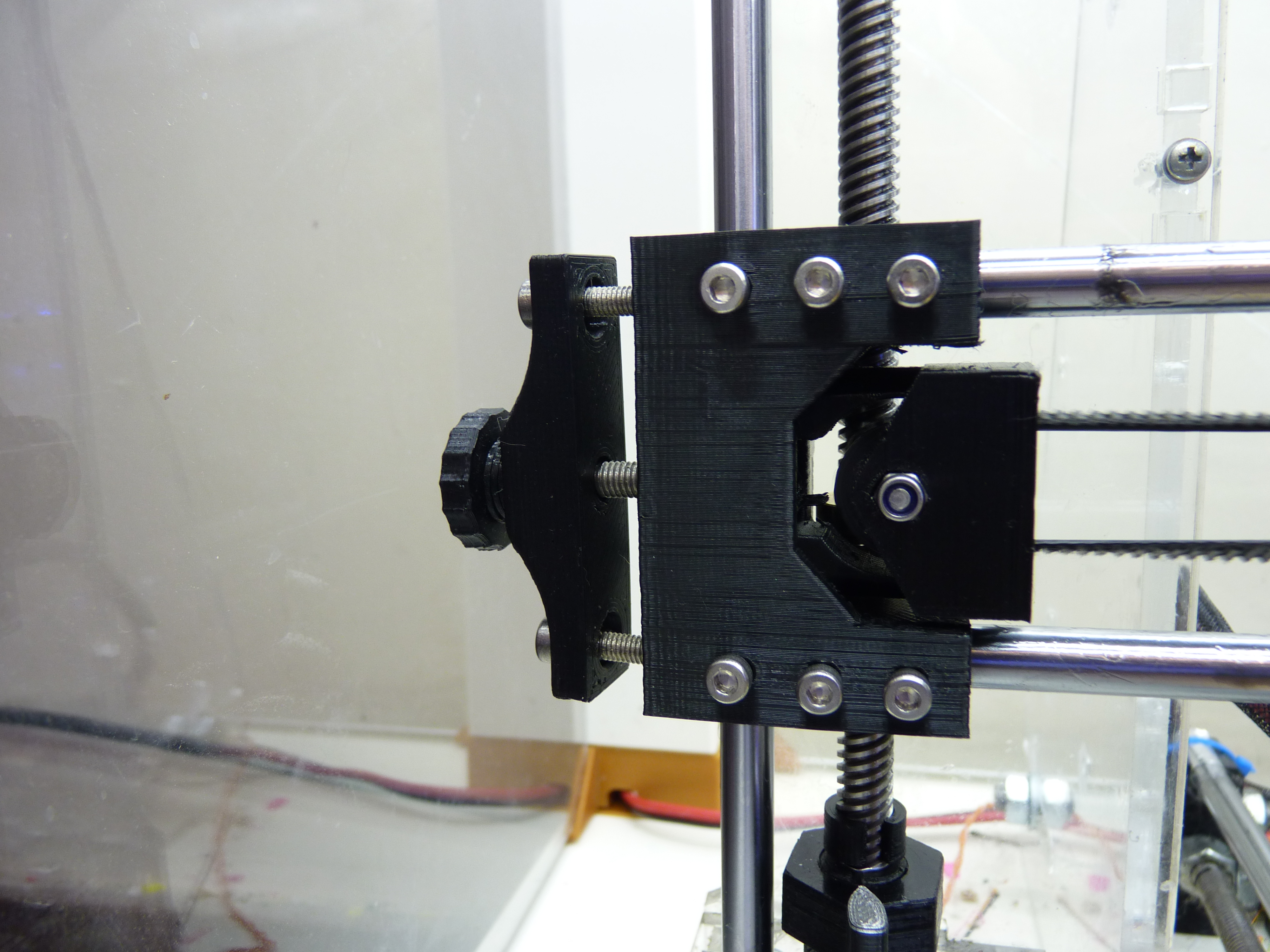
<p>This is a remix of Whitehawk2000's X/Z ends for leadscrews on the Prusa i3 (<a href="https://www.thingiverse.com/thing:1797165">https://www.thingiverse.com/thing:1797165</a>), plus a new X carriage made from scratch, and a new Y carriage remixed from molak34's well-tested design (<a href="https://www.thingiverse.com/thing:761813">https://www.thingiverse.com/thing:761813</a>), all designed to mount their bearings with proper clamps using screws and nuts, instead of zip ties. Plus, I've added a few related goodies. Taken together, this selection of parts makes a significant upgrade to the most important parts of the i3's X/Y/Z axes.</p> <p>These parts are meant for older Prusa i3 MK1 clones; they are not intended for genuine Prusa i3's (though they may still work if you're adventurous and your i3 needs the parts).</p> <p>I've altered Whitehawk2000's X/Z ends as follows:</p> <ul> <li>13 mm center hole for the leadscrew nut, to make room for the anti-backlash spring</li> <li>X idler pulley holder (part of the tensioner assembly) has a cut to make room for the anti-backlash nut's endcap, and it now accepts Prusa's standard 623ZZ-based "belt guide" (i.e. the vanilla singleplate model), though the pulleys included here are a bit different from those.</li> <li>Re-cut bolt/nut holes in the idler pulley holder and thumb wheel to accept M5 hex bolts (because those are all I have with hex heads :-P )</li> <li>Added an M5 nut trap to the idler pulley tensioner and made it much thicker.</li> <li>Increased the in-model diameter of the smooth rods' holes in the X/Z ends to about 8.3mm, to account for normal shrinkage and quantization errors that always happen with horizontal holes.</li> <li>Added support columns to the X/Z ends, one set of which is intended to be broken off (the ones on the idler end), so that slicer-provided support material isn't needed</li> <li><p>Added nut traps and screw holes to the X ends to allow you to clamp the X rods into place (probably not needed on most machines).<br/> The X carriage was modeled from scratch, using the original i3 carriage as a visual guide. It is a drop-in replacement, into which three LM8UU, or one LM8UU and one LM8LUU (long) bearings or equivalent bushings can be mounted, with proper screw clamps (which, aside from casting the old zip ties into the pits of hell where they came from, :-) make it easy to adjust the compression/preload if you use bushings such as Igus drylin RJ4JP-01-08). It has extruder mount holes at 24 and 30 mm spacings. The carriage is printed sitting on one edge (with supports).</p> <p>45 mm center-to-center between the X rods, 17 mm center-to-center between each leadscrew and its neighboring Z rod.</p> <p>As mentioned above, the Y carriage is remixed from molak34's design, to which I've added bolt-in bearing mounts sized for LM8UU bearings (of course), with preload/clamp screws. Note that this remix sits a bit taller than the original part, in order to make room for the bearing mounts and leave enough clearance between them and your printer's frame. I also scaled the four corner screw holes in the carriage part to 3.5 mm diameter, and beveled the bottoms of the belt clamp nut traps. I've included the belt clamp, and the side piece I use, which fits a standard ~210x210 mm bed (you'll have to rotate the side piece by 45° to print it on that bed size).</p> <p>Also included in this project:</p> </li> <li><p>A modified version of AndrewBCN's dual-623ZZ belt guide/pulley (<a href="https://www.thingiverse.com/thing:602435">https://www.thingiverse.com/thing:602435</a> - with much wider, thickened flanges, and tapered at the middle)</p> </li> <li>loco's self-centering 5-to-8 mm motor-to-leadscrew coupler with nuts, (<a href="https://www.thingiverse.com/thing:602481">https://www.thingiverse.com/thing:602481</a> - unmodified, not present in the .blend)</li> <li>My remix of jamesarm97's Y belt tensioner to use M3 screws (from <a href="https://www.thingiverse.com/thing:98786">https://www.thingiverse.com/thing:98786</a>).</li> <li>Spacers in 1, 2, 4, and 8 mm thicknesses, in case your X belt tension bolt is too long; just stack them between the knob and tensioner bar, as needed.</li> <li>Washer-like clamps for the corners of your print bed's glass. There are two variants: one for 8x8 inch (or 200x200 to 203x203 mm) glass, and one for 213x200 mm glass. (assuming your bed is the usual 213x213 mm PCB). Print 4 of these, in whatever material you can use with the hottest glass temperature, since these will be in contact with the cooler parts of the bed and glass (ABS works for me).</li> <li>A simple U-clamp that fits over the front-bottom and rear-bottom threaded rods to clamp your Y frame to some kind of base (e.g. a flat piece of hardwood, or to a table, as I did)..</li> <li>A simple switch mount that clips onto the Y frame's front threaded rods, into which you can mount a common rocker switch that you might want to use for main power. It has two additional holes that are intended to hold a small low-power toggle or push-button switch and an LED. How you wire those is entirely up to you (I used it as a cutoff switch for some extra layer fans, with the LED wired to light up when the fans were turned off). You'll need to flip the right half over for best results.</li> <li>A base piece to insert under your Z motors to force them to sit square to the frame (assuming your frame is square to the table, which it's supposed to be).</li> <li>Foot pieces you can insert between the printer and every point where it contacts the table, and little slips to put between the aforementioned U-clamps and the threaded rods they go on, to help reduce noise (print in TPU or another flexible filament, of course).</li> </ul> <p><strong>IMPORTANT:</strong> As with any complex assembly, please make sure the machine you print these on is properly square (X/Y, X/Z, Y/Z) and that your X, Y and Z steps/mm are properly calibrated, or you'll end up with distorted parts, which will negatively affect the final alignment of your Z rods, bearings, leadscrews, and X carriage (hence the extruder you hang from it).</p> <p><strong>Special notes:</strong></p> <p>If you find that your X rods are too short to poke out of the X/Z idler end (as mine were, because they're standard i3 length), drill a ~3.5 - 3.8 mm hole through each end of the tensioner bar, to allow you to drive in a pair of M4 screws long enough to reach the X rods' ends (let the screws cut their own threads).</p> <p>After printing, you may still need to ream the X rods' holes out with an 8 mm drill (you need to get the rods to slide in without a bunch of effort).</p> <p>After assembling, make sure your Z rods are perfectly parallel to the leadscrews. If they aren't, you can compensate by adding washers between the lead screw nuts and the X/Z ends (but see above about squaring your axes properly).</p> <p>Once you're sure they're parallel, do the other side, then assemble the X/Z ends, X rods, and leadscrews and hold the assembly up with X parallel to the floor, allowing the leadscrews to dangle. Make sure the lead screws appear to be at right angles to the X rods, then tighten the bearing clamps as appropriate.</p> <p>You will most likely need to either mangle the bottoms of the leadscrews, or wrap something sticky/tacky around them, so that when you put the leadscrew/motor couplers on, they maintain a strong, reliable grip on the leadscrews. A piece of a rubber exam glove or dish-washing glove should work; I used a piece of an old CPAP mask cushion.</p> <p>The Y bearing holders are a little tricky: press two nuts into the traps in the round end, then using a small Allen wrench or precision screwdriver to guide two more nuts into the traps hidden in the middle. You'll find it easiest if you slide one nut into place, squeeze the bearing mount slightly to hold the nut still, then slip the Allen wrench through the screw hole, and then squeeze the bearing mount together as far as it will go, to set the nut into place (making sure it's rotated properly to fit the trap, of course). The two nuts that go onto the bottom side will probably not stay by themselves (they need to just barely be loose, to avoid splitting).</p> <p>When you put the Y carriage together, leave the bearing mount screws loose. Slide one of your Y linear rods into one pair of bearings/bushings, then add screws and set the preload (if you're using that). You want the rod to slide easily through the bushings, without any sideways wiggle. Once that's set right, do the other pair. Do not use just any linear rods - you want to match the bearings'/bushings' preloads to their respective Y rods, as the rods' diameters may vary. Next, assemble the rods and carriage onto your machine and lock everything into their normal positions. Tighten the bearing mounts' screws, check that the Y carriage moves freely and smoothly, then loop the belt over the motor's pulley and tension it.</p> <p>Sorry for the crappy photo of the Y carriage. While I had a spare bearing mount to snap a good photo of, I didn't think to take one of the assembled Y carriage until I had already put it into service. Sorry for the print quality, I haven't yet calibrated the filament I printed it with (I just wanted to get it printed and running, didn't care if it looked all that good).</p> <p><strong>Vitamins:</strong><br/> lots of M3 x 8-14 mm screws<br/> 3, M3 x 20 mm screws<br/> 2-4, M4 x 30-40 mm screws (optional)<br/> 1, M5 x 30-35 mm screw with hex head (main idler tension screw)<br/> A bunch of M3 nuts (nylock where possible)<br/> 1, M5 nut<br/> 4, 623ZZ bearings (idler pulleys)</p> <p>Optional:</p> <p>These parts are sized to allow you to just press your bearings into place if you don't need to clamp them (i.e. if your printer over-extrudes a little, or if your bearings just hold without problems), but if you wish to clamp them down, of course you'll need more screws, and I suggest using nylock nuts where possible.</p> <h3>Changelog</h3><p><strong>2020-01-13:</strong> Added a variant of the bed corner clamp for 213x200 mm glass, as found on some machines.</p> <p>2019-12-09: Thinned-out the inner-end of the the X motor end piece - the extra thickness were preventing my X end stop from sitting properly. This deletes the two left-most screws but that won't be a problem. The thickness of that section is now about what it was in the original model it was remixed from.</p> <p>2019-11-22: Swapped the screw head recess and nut trap on the X pulley tensioners, so that the screw goes in from the front (the nut and end of the screw were interfering with something on my extruder).</p> <p>2019-11-04: I had a problem with my X belt "climbing" the sides of its pulley, so I've widened the flanges on it, and also steepened the central taper slightly, and flattened the inside surfaces of the flanges. The belt doesn't climb anymore. :-) Also, I increased the side-to-side clearance for the pulley in the X and Y tensioners slightly, and deepened the bearing recesses in the pulleys very slightly, to accommodate slightly-too-thick bearings. On the X tensioner, I made the narrow part considerably wider, stopping several tenths of a millimeter from the sides of the cavity it sits in in the X idler end, both to make it stronger and to reduce the play between it and the idler end.</p> <p>2019-08-14: Reworked the X carriage supports - they are now much easier to remove, and come off fairly cleanly.</p> <p>2019-03-22: My frame has gotten warped, twisted, and cracked and just turned to crap over its lifetime, and lately this has demanded some way to help hold it square, so I've thickened the front surfaces of the X ends, and added nut traps and screws to both, to let you clamp the X smooth rods in hard. Three screws per rod, per side (total 12).</p> <p>2019-01-12: Made the pulleys' flanges much thicker (from the inside, thus reducing the belt path to 7 mm, which should be fine since 99% of printers use a 6 mm wide belt) and increased the middle taper a bit.</p> <p>2019-01-07: Made them thicker again, but not enough to hit my sensor this time. :-P</p> <p>2018-07-16: Thinned the bed corner clamps considerably - my inductive sensor was brushing against one corner.</p> <p>2018-07-10: Added my remix of molak34's Y carriage with bolt-on bearing mounts.</p> <p>2018-06-16: Got rid of the Y carriage and bearing mounts. What I made didn't work as well as I thought - it vibrates too much with Y axis movements.</p> <p>2018-06-11: Added my remix of jamesarm97's Y belt tensioner, my bed glass corner clamps, a simple U clamp for the bottom rods in the front and back of the Y frame, and a clip-on rocker switch mount.</p> <p>2018-06-07: Added custom X and Y carriages, turning this into a more complete carriage/gantry upgrade kit.</p> <p>2018-06-02: renamed everything, named the existing ends and pulley holder "inverted", added non-inverted versions to let you put the leadscrew nut on the bottom if you have room to do so (that way the anti-backlash part pushes down on the gantry instead of up). Switched out the stock pulley for AndrewBCN's dual-623ZZ pulley.</p> <p>2018-02-09: Increased the clearance around the spring and anti-backlash cap.</p> <p>2018-02-06: Minor rework of the "support columns" on the idler end - they're a bit thicker and have a connecting bridge between them to help avoid them being knocked over while they're printing, and I've redone the deliberate weak spots (in the thickest parts) to make it easier to break them off when the part is finished. I also added narrow cuts to both idler ends, similar to what I did on the idler pulley holder, to make sure your slicer has a good place to put the seams when it goes to do the overhanging bits near the tops. I've thickened the walls of the idler pulley holder very slightly to make it slice cleaner</p> <h3>Print instructions</h3><p><strong>Rafts:</strong> No<br/> <strong>Supports:</strong> No<br/> <strong>Resolution:</strong> 0.2 mm<br/> <strong>Infill:</strong> 40-60%</p> <p><strong>Notes:</strong></p> <p>Print slow, and pay attention to how your slicer handles the X idler pulley holder and the leadscrew nuts' flange mounting holes (particularly the thinnest bits).</p> <p>For strength, the X carriage is printed lying on one edge - it has its own support objects, but you can omit them in favor of what your slicer provides, if you want.</p> <p>The Y carriage should be printed in ABS or something else that's hard and heat-tolerant, but the bearing mounts may be printed in PETG if desired.</p> <h3> How I Designed This</h3> <p>Blender, Blender, and Blender, with a side of coffee :-P</p>
With this file you will be able to print X/Y/Z upgrade kit for acrylic Prusa i3 clones (based on TR8 leadscrews) - No more zip ties! with your 3D printer. Click on the button and save the file on your computer to work, edit or customize your design. You can also find more 3D designs for printers on X/Y/Z upgrade kit for acrylic Prusa i3 clones (based on TR8 leadscrews) - No more zip ties!.