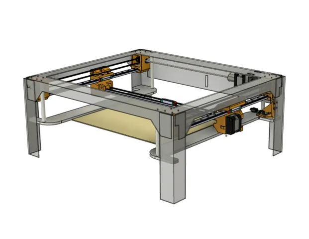
X-Max (X-Plus) Gantry Linear Rail Conversion
prusaprinters
Update 2023/2/6: Beefier left gantry to reduce the possibility of the rail twisting. Requires a 425mm long MGN12 rail.Update 2022/12/26: Improved Y-Axis Limit Switch Mount.Update 2022/12/11: Minor tweaks to improve printability such as increasing the radius of corners that touch the build plate.Update 2022/11/7: Lowered the belt clip profile, beefed up the X-Axis motor mount, and increased the adjustment range of the Y-Axis limit switch mount. Also added a link to a SherpaMicro Extruder and Carriage.Update 2022/10/24: Added instructions for adjusting the X,Y steps to accommodate the change from 17 to 20 tooth pulleys.Linear Rail UpgradeReplacing the 10mm rods on the X-Max (X-Plus) with linear rails results in quieter/smoother operation, allows for higher quality prints and increased speeds. This gantry setup weighs 40% less and slides much more smoothly than the stock Qidi gantry (50% if the X-Axis stepper motor is replaced with the motor listed in the BoM). The upgraded belt and pulleys decrease backlash and increase consistency of movement. I am amazed how quiet the printer is now. The only sound comes from the layer fan.I have included the STEP files to facilitate remixes and alternative configurations.An associated BMG type extruder/carriage can be found here: https://www.printables.com/model/266935-x-max-x-pro-linear-rail-upgrade-carriage-for-bmgdrAn associated SherpaMicro extruder/carriage can be found here: https://www.printables.com/model/313321-x-max-x-pro-linear-rail-upgrade-carriage-for-sherpFeatures:Completely reversible with no modifications to the stock parts.Adjustable belt tensioners.One bearing size. The stock left side gantry pulley uses 5x11x4mm flange bearings. This design uses 5x13x4mm throughout to save the cost of buying two sets of bearings.Uses inexpensive Linear Rails. Guidance on how to make inexpensive rails serviceable is available here: https://clevercreations.org/clean-repair-linear-guide-rails/Printing:All the files are designed to be printed as orientated without supports.Warping is a challenge, but the parts are designed such that they still work with some warping.Use the stiffest filament you can. I am using Priline’s Super Hard carbon fiber PC. I found that the gantry parts need to be really stiff, rigid, hard, strong, no deflection, etc. I recently reprinted using a PETG/PC blend and had first layer adhesion issues. Turned out that blend flexed just enough that the extruder was forced up by the pressure at the tip of the nozzle.I do not recommend any Nylons, with or without CF, they are too flexible and prone to deformation when warmed with pressure applied. Enhanced PLA might work if you are not planning to print in hot chamber.I used 6 walls, 6 top, and 6 bottom layers with 50% cubic infill and infill 40% overlap. All my other setting adjustments are based on flow cubes and temp towers.Post Printing:The corner brackets and clamps each require eight inserts. Make sure the inserts are flush with the tops of the corner brackets.The right gantry needs two inserts for the belt base and one insert for the rail pocket. Make sure the belt base inserts do not interfere with the linear rail guides.The left gantry needs two inserts for the belt base and two inserts for the rail pocket. Make sure the belt base inserts do not interfere with the linear rail guides.The Y-axis limit switch mount uses M3 nuts instead of inserts.The right and left gantry belt bases require one M3 nut each.Disassembly:This upgrade requires access to the top of the steel frame, which requires removing the plastic top cover. Unfortunately, the top cover is trapped by the side, front and back panels so some disassembly is needed.Follow these steps to remove the top and access the old gantry.Unplug the printer.Remove the extruder/carriage.Remove the sides. There are six screws on each side accessible from the outside and one screw on each side above the hand hold on the inside.Remove four screws on each side of the top.Remove the top three of the four screws on the each side of the front panel.Loosen the bottom screws on each side of the front panel.Remove the one screw on the inside of the top of the front panel.The front panel should now rotate away from the frame enough to expose the trapped top front lip.Remove the top two screws from each side of the back.Remove the one center screw from the top of the back.Flex the back to expose the back lip of the top.You should now be able to lift the top off the frame.Removing the stock gantryUnplug the stepper motors. There may be hot melt glue on the connectors that needs to be pried off.Unplug the limit switches.Cut the zip ties holding the drag chain to the right hand gantry end.Pull the belts out of the gantry ends.Pull the left side gantry end piece away from the bed to dislodge the bearings so that the X-axis rod can be removed from the pocket. Note: It is easiest to cut the X-axis belt, but it is possible to manipulate the gantry ends to remove the belt without cutting.Remove the four screws holding the motor on the right side gantry piece.Pull the right side gantry piece off of the bearings.Removing the Y-axis rods and corner brackets Because the rod ends are in pockets we need to do more than just remove the screws holding the brackets. We need to be able to pivot the rod away from the frame to get clearance, however to do this we need to remove the front Z-plate support posts. Fortunately this is easy to do with just a top and bottom screws for each post.Loosen the four screws holding each corner and the two screws holding the Y-axis motor. Note: you may find it is impossible to remove some of the screws without stripping the screw's hex socket. In these cases, carefully drill out the screw's head. Be careful; it is really easy to go too far and drill into the frame. I set all these button head screws aside for use on the linear rails and replaced with cap head screws.With all the screws loosened, we can now remove all the screws without stressing any parts.With all the parts removed, reinstall the Z-axis posts.We need to keep the front corner shafts and the left gantry shaft, but all the stock pulleys and spacers can be set aside.Remove the Y-axis limit switch bracket and set aside.AssemblyIf you bought a 450mm rail for the X-axis gantry, cut it down to 425mm (or a smidgen less). I used an angle grinder with a metal cutting disk. I kept the plastic wrap on the rail to keep shavings out of the bearing.I recommend replacing the rubber stops on the rails with screws to ensure the guides don't slide off during assembly.Make sure the X-axis rail ends fit snuggly into the gantry ends. The screw on the back of the left side gantry should not protrude into the rail pocket. This screw allows for adjusting depth of the linear rail so that the gantry ends are perpendicular to the rails.Cut the new Y-axis belts to length, adding about 10mm which can be trimmed back later.Loose fit the pulleys and spacers on the shafts. The pulleys on the Y-axis drive need to be orientated such that the grub screws engage the flats on the shafts.At this point the grub screws need to be tight enough to prevent rotation while still allowing the pulleys to slide. Position the pulleys such that the grub screws are closer to the center of the the printer rather closer to the frame.While the drive assembly is still outside the printer, fit the spacers and corner brackets.Wrap the belt ends around the pulleys and use clips on the belts to hold the pulleys in place.Note: Use binder clips to keep the belts from falling out. Installing the belts after the corner brackets are in place is no fun at all.Position the assembly and hold in place with a few loose screws, then install the rest of the screws and snug them up, but don't fully tighten yet.Tighten the pulley grub screws on the drive shafts.Fit the belt tension bases and sliders on the belt loose ends. These will act as weights to keep the pulleys in the front corner brackets from falling out while brackets are fitted. Note that the pulley orientation needs to be the same as the drive pulleys and the E-clips are positioned such that they are next to the frame. No grub screws are needed for these pulleys. Tighten the grub screws on the drive pulleys.Because there is not much clearance between the frame and the top of the gantry end pieces we need to drill one 6.5mm (¼") access hole in both the top left and right frame rails about one third of the way from the front or back. On the right rail, 20mm from the inside edge and on the left rail, 22mm from the inside edge. The idea is to provide a means of accessing the screws from above. Only one hole is needed because the gantry assembly can be moved back and forth under the hole.Optional: Assemble the gantry ends onto the rails and the belt clip bases onto the gantry ends before installing the rails into the corner brackets. Then Insert the X-axis rail into the right gantry with the guide facing to the back of the printer.Position the right side rail and hold in place with the corner bracket clamps. Again, just a snug fit.Position the left side rail, fit the rail into the pocket and then hold in place with the corner bracket clamps.Trial fit the X-axis rail in the gantry ends.Loosely install the right gantry end on the right Y-axis rail.Press in the X-axis rail.Install the left gantry end on the left Y-axis rail while also pressing the X-axis rail into the socket. Support the right gantry end. The left gantry mounting holes should be directly over the holes in the left Y axis bearing without any twisting or rotation.Tighten all the corner bracket and drive assembly screws in turn, a bit at a time, except for the clamps. These screws are tightened later.Tighten the screws that hold the gantries on the bearings. Make sure the gantry ends are aligned vertically. Adjust the left side gantry back screw as needed.Install the Left Gantry clamp.Loosen one of the grub screws on the Y-drive couple. This will allow the left and right pulleys to rotate independently. The grub screw will likely be quite tight.Connect the belt tensioner sliders while making sure the belts are positioned on the pulleys correctly.Install the tensioners onto the gantry ends.Move the gantry ends as needed to bring the gantry to square. Test squareness by measuring from the left and right end X-axis rail edges to the frame.Tighten the X-Drive couple grub screw loosened earlier.Run the gantry from front to back a few times to bring the rails into alignment and then tighten the corner clamps.Install the pulley on the X-axis motor with the teeth away from the motor body.Install the X-axis motor into the right side gantry.Zip tie the drag chain to the right side gantry and connect the motor.Connect and install the X-axis limit switch.Mount the Y-axis limit switch to the mounting bracket and then install the mounting bracket onto the frame.Install the carriage belt, left side gantry pulley and carriage belt tensioner.Install the carriage and verify the limit switches are working as expected and all clearances are good.Changing to 20t pulleys necessitates adjusting the X and Y steps.Steps:Save a current copy of the configuration by creating a text file named ConfigExtract.gcode with the following contents then print it (run it) and copy the results off of the USB to a safe place.M8512 'ConfigFile.gcode'Create a file named UpdateXYSteps.gcode using a text editor, enter the following text and then print it (run it):M8998 I1 ; enable configuration (that is the letter ‘eye’ before the 1)M8009 S0.012500M8510 ; ApplyM8500 ; Save Clear the USB and then rerun the ConfigExtract.gcode to verify that M8009 is set to 0.012500.BoM:Linear Rail Guidance: https://clevercreations.org/clean-repair-linear-guide-rails/DescriptionAmazon U.S.ImageMGN12 400mm Linear Rail Guide with MGN12H Stainless Steel Carriage Blockhttps://a.co/d/i9EhWGsMGN12 450mm Linear Rail Guide with MGN12H Stainless Steel Carriage BlockNeeds to be cut down to 425mmhttps://a.co/d/crkPM4C20T GT2 Aluminum Pulley, 5mm Bore, 6mm Widthhttps://a.co/d/aocGlYn5 Meters GT2 Timing Belt, 6mm Widthhttps://a.co/d/59j4PzW5x13x4mm Flanged Ball Bearingshttps://a.co/d/hFvVUVkM3x5.7mm, OD4.6mm Threaded Brass Inserthttps://a.co/d/6rNIbp1Stainless Steel M3 Hex Socket Head Cap Screws and Nuts Assortmenthttps://a.co/d/1ef5smv
With this file you will be able to print X-Max (X-Plus) Gantry Linear Rail Conversion with your 3D printer. Click on the button and save the file on your computer to work, edit or customize your design. You can also find more 3D designs for printers on X-Max (X-Plus) Gantry Linear Rail Conversion.