Wireless powered Bambu Lab Bento Box Air Purifier for X1C / P1P
prusaprinters
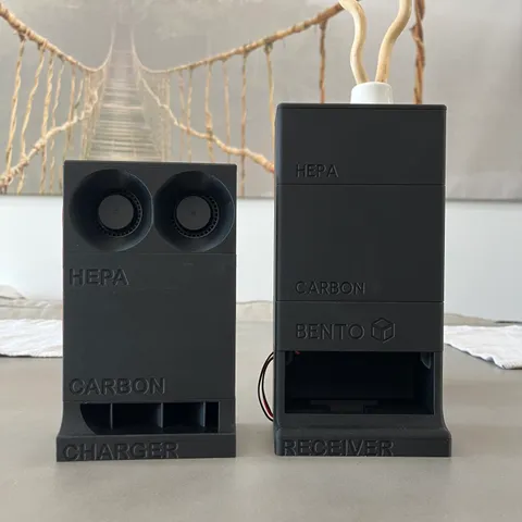
UPDATES: April 7th: Added support for 24V 4020 fans on V2 design (should also work for V1 designs). If using 24V fans, trim the boost converter output to 24.0 instead of 12.0 April 7th: Added “wireless test jig” to help with assembled coil testing before installing the enclosure. Simply mount the transmitter box into the allotted space and align the receiver box on the debossed corner. The receiver coil should be over the non-perforated region of the base. WIRELESS POWER:The major change here is that I added an wireless receiver module to the bottom of the assembly coupled with a wireless transmitter module for installation under the unit. Alignment between the receiver and transmitter was determined via a 3D scan of the X1C and should be as close to perfect as you can get in X, Y, and Z (z-distance matters as much as X and Y). Everything is magnet or friction fit installable and requires no modification to the printer housing. Power is supplied via an external micro-USB port and the instructions provide parts for a completely solder-free assembly. V2 BENTO BOXPrinted PartsFan Duct 6x3 magnets or Fan Duct 4x2 magnetsReceiver Box 6x3 magnets or Receiver Box 4x2 magnetsWireless Transmitter BoxWireless Transmitter Cover(OPTIONAL) Wireless Test Jig(From Bento Box Creator)Cover_voronoi or Cover_hempHepaCarbonFan caseCMag Case 01CMag Case 024x net_infillBentoBox20 User Guide Materials12V 4020 Fans or 24V 4020 FansWireless ReceiverWireless TransmitterBooster Converter 3-35V with LED Voltmeter (alternate: source 1, source 2)Wire Connector (for solder-free option)USB Charger (minimum 2A)Flat micro-USB to USB A cable6mmx3mm disc magnets or 4mmx2mm disc magnets (depending on version)Hepa FilterActivated Carbon Pellets and alternative vendor (MUST BE ACID-FREE)Brass inserts (M3xOD5mmxL4mm) INSTRUCTIONS:Assemble Wireless Receiver1) Use the wire crimper, or a soldering iron, to connect the receiver 1) Following V1 instructions as reference, install the receiver coil into the V2 receiver box Assemble wireless transmitter1) Install the wireless transmitter into the transmitter box by carefully laying the coil (coil side down) into the box. Note: This is definitely the most sensitive step in the installation. The ferrite disc is extremely brittle and can easily crack from point forces. If the disc breaks, the transmitter will likely drop enough in efficiency that it will no longer transfer enough power to run the fans. Because of part-to-part variation, you may need to fiddle a bit to get the coil to sit properly in the housing. It is critical that the coil lay flat in the housing.2) Slot the transmitter PCB into its port and push it down onto the retaining clip.Note: Because of part-to-part variation, you may need to fiddle a bit to get the PCB to sit properly in the housing. Pull back on the retaining clip, but be careful not to snap it. Trim power converter1) The boost converter linked has a variable output and needs to be trimmed to 12V (for 12 fans) or 24V (for 24V fans) before assembling. Do this by powering the assembled wireless transmitter and centering the assembled wireless receiver on top of it. 2) Use the wireless test jig to align the coils3) If the coils are properly aligned, the display should illuminate. You may need to press the IN button to turn on the display.4) If the display reads 5V, press the OUT button to change the output to the converted voltage.5) Turn the potentiometer near the power led until the LED displays 12V or 24V (depending on fans chosen). If the display does not change value, press the out button and try again. Install boost converter into receiver box1) After cutting the ends off the fan wires (be careful not to cut the wire too short, extra slack is better than not enough), mount the boost converter onto the standoffs in the receiver box Align fan duct onto receiver box1) Place the fun duct on top of the receiver box and align the boost heat sink and display into the fan duct holes. Assemble and install Bento Box1) Assembly the individual modules, magnets, add carbon pellets, and hepa filter into their respective boxes.2) Gain access to the underside of the X1C3) Install the transmitter box in the space provided. Make sure you push it flush against the underside plastic.4) Route the micro-USB out the back of the system. Install Bento BoxIf all went well, the Bento Box should power up once it is placed in the system Instructions for previous version of the Bento Box (V1) FOR V1 BENTO BOX (OLD DESIGN):MATERIALSPrinted PartsFilter box, carbon box, and fan box (depending on version) can be reused from existing solutions. All other parts need to be printed. Purchased Parts12V 5015 FansWireless ReceiverWireless TransmitterBooster Converter 3-35V with LED Voltmeter (alternate: source 1, source 2)Wire Connector (for solder-free option)USB Charger (minimum 2A)Flat micro-USB to USB A cable6mmx3mm disc magnetsHepa FilterActivated Carbon Pellets and alternative vendor (MUST BE ACID-FREE) INSTRUCTIONS:Assemble wireless receiver1) Install the wireless receiver into the charger box by first inserting the circuit board and then the wireless coil. NOTE: Because of part-to-part variation, you may need to fiddle a bit to get the coil to sit properly in the housing. It is critical that the coil lay flat in the housing.2) Place the ferrite block over the receiver and note the overhang distance.3) Use a sharp pair of scissors to cut the ferrite block such that it will lay in the receiver housing 4) Either solder or use the linked connectors to extend the receive wires by about 8 inches. Assemble wireless transmitter1) Install the wireless transmitter into the transmitter box by carefully laying the coil (coil side down) into the box. Note: This is definitely the most sensitive step in the installation. The ferrite disc is extremely brittle and can easily crack from point forces. If the disc breaks, the transmitter will likely drop enough in efficiency that it will no longer transfer enough power to run the fans. Because of part-to-part variation, you may need to fiddle a bit to get the coil to sit properly in the housing. It is critical that the coil lay flat in the housing.2) Slot the transmitter PCB into its port and push it down onto the retaining clip.Note: Because of part-to-part variation, you may need to fiddle a bit to get the PCB to sit properly in the housing. Pull back on the retaining clip, but be careful not to snap it. Assemble power converter1) The boost converter linked has a variable output and needs to be trimmed to 12V before assembling. Do this by powering the assembled wireless transmitter and centering the assembled wireless receiver on top of it. 2) Use the wireless test jig to align the coils3) If the coils are properly aligned, the display should illuminate. You may need to press the IN button to turn on the display.4) If the display reads 5V, press the OUT button to change the output to the converted voltage.5) Turn the potentiometer near the power led until the LED displays 12V. If the display does not change value, press the out button and try again. Assemble fans1) Cut the fans so that the have about 6 inches of wire length and strip the ends. This will make installation into the fan box much more manageable2) Connect the extended receiver cables into the INPUT of the boost converter. The red wire (+5V) goes into IN+ and the black wire (GND) goes into IN-3) Connect the fan wires into the OUTPUT of the boost converter. The red wire (+12V) goes into the OUT+ and the black wire (GND) goes into IN-4) Place the receiver on a powered transmitter and confirm the fans power on.NOTE: If the fans power on and off, check the alignment of the coils. You may also need to place a small spacer between the transmit and receive coil to get the optimal distance. The assembly is tuned for installation in the printer so getting them to run outside of the box is a bit nuanced. Install fan and converter into fan box1) Starting with the assembled receiver, converter, and fans, slot the fans into the fan box such that the fan outlets align with the fan box outlets.2) Slip the Boost converter into the rear compartment and tuck the wires into the available space Final CheckConfirm once again that both the receiver and transmitter coils are sitting flat in their housing and that the receiver coil has it's provided ferrite block and that the transmitter coil ferrite disk is not cracked. Assemble and install Bento Box1) Assembly the individual modules and add carbon pellets and hepa filter into their respective boxes.2) Gain access to the underside of the X1C3) Install the transmitter box in the space provided. Make sure you push it flush against the underside plastic.4) Route the micro-USB out the back of the system. Install Bento BoxIf all went well, the Bento Box should power up once it is placed in the system Feel free to drop any questions you might have during installation and I will be happy to help!ENJOY!
With this file you will be able to print Wireless powered Bambu Lab Bento Box Air Purifier for X1C / P1P with your 3D printer. Click on the button and save the file on your computer to work, edit or customize your design. You can also find more 3D designs for printers on Wireless powered Bambu Lab Bento Box Air Purifier for X1C / P1P.