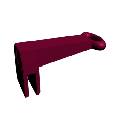
Wire guide for Prusa I3 printer
cults3d
The Prusa i3 rework printer is a highly acclaimed DIY kit that requires precise assembly and calibration to achieve optimal results. To ensure a smooth printing experience, it's essential to carefully follow the provided wire guide. Begin by identifying the various components of the printer, including the frame, X-axis carriage, Y-axis carriage, hotend, and extruder motor. Next, locate the corresponding wires for each component and label them accordingly using a marker or tape. The X-axis motor should be connected to the motherboard via a 4-pin JST-XH connector. The Y-axis motor should be connected to the same motherboard using a separate 4-pin JST-XH connector. Ensure that both motors are properly seated on their respective mounts and securely attached to the frame. The hotend temperature sensor should be connected to the motherboard using a 3-pin JST-XH connector. The extruder motor should be connected to the motherboard using a 2-pin JST-SH connector. Finally, connect the power supply to the motherboard using a standard IEC C7 power cord. Double-check all connections and verify that each component is properly seated and secured. Test the printer by running a diagnostic program or printing a simple calibration object.
With this file you will be able to print Wire guide for Prusa I3 printer with your 3D printer. Click on the button and save the file on your computer to work, edit or customize your design. You can also find more 3D designs for printers on Wire guide for Prusa I3 printer.
