WeldingRod Bot: Exactly Constrained 3D Printer
thingiverse
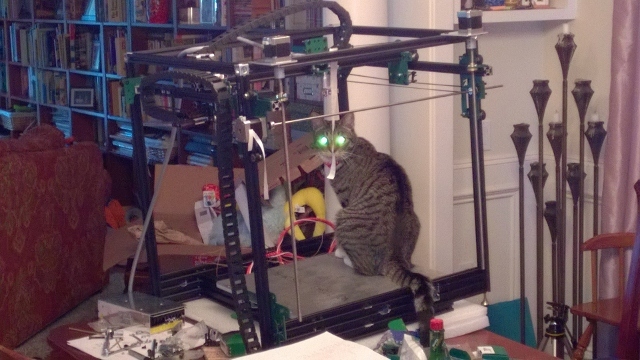
A 3D printer based on the Cobblebot kit or OpenBuilds parts is being designed to achieve smooth motion with minimal adjustment by avoiding over-constraint. I'm printing now! *** The name Cobblebot is a trademark of Cobblebot Inc. This work uses their kit of parts for a "Basic" design, but it's radically different from their original concept. *** I'm working on a modified build for the Cobblebot or OpenBuilds parts to achieve smooth motion with minimal adjustment. The revised version will use new plates designed after the initial fitup on AA, and the ability to mount hot ends under the X carriage has been added. Lessons learned from Rev E include: * Corner blocks do not ensure rails are rotated square to other rails * Planned end stop locations interfered with parts * Belts were kind of short * Parts of the Y ran into the base * X rail was hard to install * Not enough idler mounts were purchased The AG revision is designed, and now it's time to get it cut. Lots of rounds of cut/print, and try... I'm hoping Revision AK is the magic one! I got my Keenovo heater/temperature controller installed this weekend onto my 3/8" thick aluminum build plate (I know, excessive). Dang that thing heats fast! When I set it for 40C, I could feel the silicone heater warm up in 1 or 2 seconds! In my "mad scientist/engineer" mode, I couldn't resist adding instrumentation ;-) Four miniature wire thermocouples are set at center, 50, 100, and 150 mm radius, and a separate thermistor is used. I test fit 3d printed AK version plates this morning; I think I have it now! Mwa-ha-ha-ha! Ok, AK got the belts almost right, and got the X endstop to work BUT, the Y endstop hit the top frame and the X belt idler hit the top frame. Argh! On to AN and AM. OK, Revision AP for the frame plates is the winner! The motions line up nicely, run smoothly without adjustment, the belts work, and the limit switches work! Time to start wiring! That, and make the magic stepper motor to shaft connector WITH a timing pulley on it. The cable chains came out well! Cutting and extending EVERY single wire... Ugh. There is a photo of what the series Z motor harness needs to look like, in case you want to make it the way I did. You can check your Z wiring by shorting each phase and turning one screw to lower the gantry; the other side should lower too. It will NOT raise this way; not enough power output! The motor you are turning acts as a generator and drives the other one. I hope to plug everything in tonight. Key item: I un-soldered one side of D1 on the RAMPS board to isolate the Mega from +12. I will use a regulator to feed the Mega with 9 Volts to bring down the power dissipation. Another tip: my prox sensor produces an inverted output. Took a while to diagnose! I am printing now; the first try on a 20 mm calibration cube looks good! I printed a test piece with the far side Y belt disconnected to see if that makes any difference in the prints. It BARELY makes any difference. I will put the belt back on, since I already have it in place, but its optional now!
With this file you will be able to print WeldingRod Bot: Exactly Constrained 3D Printer with your 3D printer. Click on the button and save the file on your computer to work, edit or customize your design. You can also find more 3D designs for printers on WeldingRod Bot: Exactly Constrained 3D Printer.
