Wanhao i3 Control Box Rear Panel for Modular Connections
prusaprinters
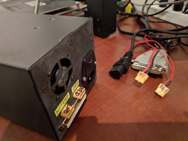
I wanted to be able to disconnect the control box of my Wanhao Duplicator i3 v2.1 from the printer, largely because this makes it much easier to mount the printer inside an enclosure (to let ABS print in a warm environment) while the control box is outside for ease of access and good cooling for the motor drivers and hotbed mosfet. This print makes it easier to do that. It's still a lot of work, though. You'll need: 2 complete xt60 connectors (male and female sides) 1 female d-sub 37 pin connector 1 male d-sub 37 pin connector 1 d-sub 37 pin connector cable housing lots of heat shrink tubing, ideally in various colors, and at least two sizes (one small enough for individual cables from a ribbon cable [maybe 1/8" or 3mm before shrinking], and one large enough to cover xt60 cups [maybe 1/4" or 6mm before shrinking]) 16-gauge or coarser wire to extend the hotend and heatbed connections ribbon cable to extend the other connectors Soldering iron, solder, heat gun Some way of making opaque marks on black wire casing (I used a yellow Permapaque marker, but nail polish or whiteout would work just as well) Small zip ties for cable management Drill New spacers for the power supply (I used 1/4" nuts) Bolts & nuts to hold the power connector, fan, and d-sub connector (I used m3's) The fact that this design requires you to move the power supply towards the front of the control box is rather a design flaw, but since I was able to make it work for me, I'm not particularly inclined to try to fix that flaw at this point. So if you want to use the same design I did, you'll probably need to move your power supply forward too. This isn't too hard; you just unscrew the power supply, drill four new holes further toward the front, and add some kind of spacer to the bolts. The spacer is required because the existing holes had sort of raised pillars around them, so you need the power supply to clear those pillars. I used 1/4" nuts, because I had them lying around. This step wasn't particularly hard, but I'm not thrilled that it's required. Be VERY CAREFUL to mark the orientation of wires before you cut them. The motor connectors in particular tend to be hooked up with unmarked black ribbon cable, so if you cut those without first making a mark along one edge of the ribbon cable, you won't know which way is which. It doesn't particularly matter what convention you use, but for the record, I marked the edge that is leftmost if you are looking down at the mainboard, such that the edge with all the connectors on it is at the top. I hooked the wire from this edge to the lower-numbered pin in each group. This isn't as critical for the endstops and thermistors, as these parts don't require a specific orientation, but I kept it up anyway, as it seemed like a good habit. My connection schema on the d-subs was this: Pins 1-4: x motor Pins 5-8: y motor Pins 9-12: first z motor Pins 13-16: second z motor Pins 17-18: extruder fan. Note that this connection runs to the power supply, not the motherboard. Pin 19: Not Connected Pins 20-23: Extruder motor Pins 24-25: Not Connected. I initially had the hotend on here, and if you d-sub has a high enough amperage rating (4A or higher) you could do this, but it's safer to use a second xt60. Pins 26-27: Part Cooling Fan Pins 28-29: X endstop Pins 30-31: Y endstop Pins 32-33: Z endstop Pins 34-35: Bed Thermistor Pins 36-37: Extruder Thermistor First XT60 connector: Heated Bed (~10A draw) Second XT60 connector: Hotend (~3A draw) Because you'll likely need to make the connections longer on most of the control-box-side connections, you'll be soldering about 68 d-sub tin cups, 8 xt60 cups, and around 34 additional wire splices. It's not for the faint of heart. Note that the pin ordering on the male connector is the mirror of that on the female connector--the male has pin 1 on the far right on the side you solder, whereas the female has pin 1 on the far left on the side you solder. This makes sense if you think about the way these things plug together, but it's kind of a "gotcha" the first time you work with d-subs. And again, remember to mark the orientation of the cables before you cut them. It's way easier to get this stuff right the first time than to debug it later. Print Settings Printer Brand: Wanhao Printer: Wanhao Duplicator i3 V2 Rafts: No Supports: No Resolution: 0.2 Infill: 100% Notes: Printed in ABS, since the control box can generate a fair amount of heat. Sorry about the orientation--it's the default in Fusion 360 and I never fixed it. Post-Printing Once you've actually got the connectors wired up and the rear plate printed, actually installing it is pretty easy. The power supply switch bolts on. I did use longer bolts and nuts to hold the power connector and fan in place, because the old ones just bolted into threads in the rear plate, and the plastic isn't really up to that task. There are only a few "gotchas" about installing the plate. First, you'll need to drill out the holes. They're in the right spots, but they're not going to be big enough. But holes always turn out kind of messy anyway, right? Second, there's a divider down the middle of the brace for the xt60 connectors, and the brace itself is fairly deep, so you can't really pass any connectors other than wires through the openings. If you've done a hotbed MOSFET mod (highly recommended), then this isn't much of an issue for the heatbed, since the wires for these will go to screw terminals. But for the hotend, you'll need to detach the connector. This is also only held on with screws, but it's an extra step. I think you'll also want to mark positive and negative before doing this, so you can reattach it in the right orientation. I'm not actually certain that the hotend cares about polarity, but it's better to be safe, right? The same procedure works for the hotbed connector if you haven't done the mosfet mod, although I'd be really surprised if you were doing this painstaking and optional procedure before that simple and safety-oriented one. Third is a similar situation with the d-sub opening; you'll need to pass some connectors through. The only ones that gave me trouble were the Fan connector and the Extruder Motor connector. The Fan connector on mine actually would fit through sideways, and the Extruder Motor connector wouldn't quite fit, but I flexed the plastic and got it through. You also have the option of unscrewing these and reattaching them on the other side. I know there have been other versions of this printer with a variety of other kinds of connectors, so if you encounter additional challenges, I apologize. Please share how you solve them in the comments. I didn't wind up using any glue or anything for the xt60 connectors. They fit pretty tightly in the support wells. You may wind up wanting superglue or sandpaper there if the fit is off when you print it. That's about it. Hope this helps someone. I really did this mainly for my own benefit, but there was some interest in the STL on the Wanhao i3 facebook group, so I'm sharing it here in the hopes someone else will get some use out of it too. Category: 3D Printer Parts
With this file you will be able to print Wanhao i3 Control Box Rear Panel for Modular Connections with your 3D printer. Click on the button and save the file on your computer to work, edit or customize your design. You can also find more 3D designs for printers on Wanhao i3 Control Box Rear Panel for Modular Connections.