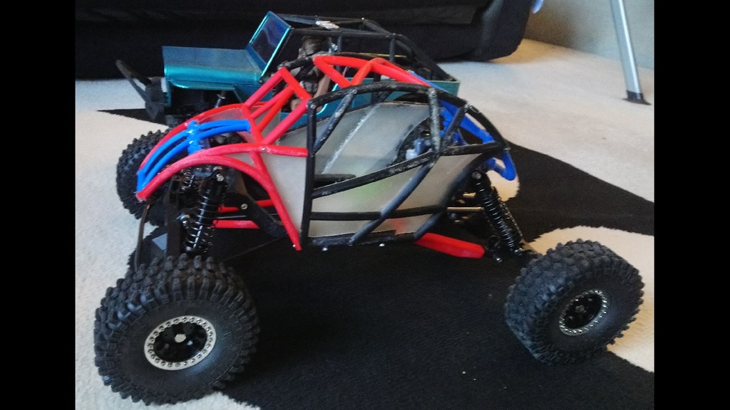
W2D-IV Trailing ARM Mod
thingiverse
Hi guys, Warning: If you have problems with part strength, be prepared to do some work on your print process if you want to have success running this crawler. It is BIG and the parts need to be strong. I had my first experience with bad (brittle) PLA while testing this and I now understand the bad experiences that some people have had. My next buy is going to be PLA+ because the added flexibility should help a lot. I'm using a batch of Solutech that I got dirt cheap, but some of it is terrible and some not bad, so take that for what you will. I found the old Amazon Basics PLA to be quite strong, for what that's worth. To get strong parts: Make them solid. Print them lying down. Use a criss cross infill pattern. Play with the heat to get it as high as you can without the plastic going brittle. Usually, right about where the stringing starts is good for me. Zero stringing is not the strongest part IMO. Over extrusion is better than under extrusion. Your mileage may vary. This is a suspension mod for my W2D-IV Baja Racer. I'm running these parts with the Redcat XR247 (Wendigo) Axle kit but any wide axles should work with a little DIY. See it running: https://www.youtube.com/watch?v=FjeaudXrbwM See it breaking: https://www.youtube.com/watch?v=MjZcI0Bl2tY Baja Racer: https://www.thingiverse.com/thing:4597812 I used longer than normal M4x20mm grub screws to attach standard crawler link ends to the rear arms but regular ones should work. My thinking was that longer would make the arms stronger. The rear trailing arm and link mounts sandwich around the chassis rail with the rear screw used to mount the trailing arm. 2x M3x20mm screws. The upper link uses an M3 screw. You'll need a LONG rear drive shaft. I used a hex slider one and modded it for more length using a long allen wrench. Cut off the 90 degree end of the long allen wrench and use that in place of the stock slider. See my how to video: https://www.youtube.com/watch?v=q1cafR62I2U The inboard servo started as a temporary work around but it seems to work well so I'm leaving it for now. I had to DIY the front linkage. The servo mounts sandwich around the chassis rail as shown in the picture and the servo attaches to the mount. If you are running XR247 axles, use Str_Axle_Mnt.stl and attach it to the axle on the right side of the pumpkin using the existing hole. Attach the Str_Crank.stl to the mount. Str_Crank_V2.stl has a larger hole for use with a bushing. I had some shock spacers kicking around that worked, so your mileage may vary. I used a soldering iron to press the bushing in like a threaded insert and it seems to be working well. Bearings would be better but I haven't gotten around to that yet. Link lengths are hole to hole and approximated (measured on the car): Front steering: 80mm Center steering: 100mm Front lower: 130mm Front upper: 125mm Rear lower: 122mm Rear upper: 135mm Drive shafts: Front: 130mm Rear: 165mm Drive to wrench or wrench to drive?
With this file you will be able to print W2D-IV Trailing ARM Mod with your 3D printer. Click on the button and save the file on your computer to work, edit or customize your design. You can also find more 3D designs for printers on W2D-IV Trailing ARM Mod.
