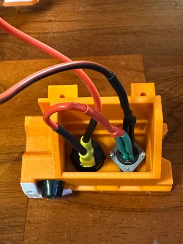
Voron V0.2 DC Inlet Foot
prusaprinters
Voron V0.2 DC Inlet FootReplaces the mains inlet foot part in the V0.2 to allow for the use of an external DC power supply (and consequently a 24V bed heater, since you no longer have mains power on the printer). This is based on the "Voron 0 DC inlet" mod by arkeet (https://github.com/VoronDesign/VoronUsers/tree/master/printer_mods/arkeet/v0-dc-inlet).BOM Kycon KPJX-PM-4S connector (https://www.digikey.com/en/products/detail/kycon-inc/KPJX-PM-4S/9990081)Mean Well GST163A24-R7B power supply (https://www.digikey.com/en/products/detail/mean-well-usa-inc/GST160A24-R7B/7703602)Power switch, 20mm round, rated for at least 7A at 24VDC (https://www.digikey.com/en/products/detail/w-rth-elektronik/471002268142/9950821)2x quick disconnect terminal for power switch (https://www.digikey.com/en/products/detail/te-connectivity-amp-connectors/2-520194-2/289254)24V 60W bed heater (https://keenovo.store/collections/standard-keenovo-silicone-heaters/products/keenovo-square-silicone-heater-3d-printer-build-plate-heatbed-heating-pad?variant=33194097803404)4x M2x10 self-tapping screw18AWG wireHeatshrink tubingImplicationsThere are several implications to not having mains power in your printer:24V bed heater can be safely run at 100% powerNo need for a 24V power supply on the printer itself means a lot more availabe roomYou can utilize a 24V-5V step down converter to power your Raspberry Pi instead of needing a separate 5V PSUI recommend using Wago lever nuts and ferules to simplify your wiring and keep it neat and tidy!InstructionsAfter printing, prepare the new foot with heatsets as per the Voron 0.2 manual.Solder the wires between the Kycon connector and the switch prior to installation. Use the quick-connect terminals on the switch side. Be sure to install heat-shrink tubing over all exposed areas. Also ensure that the inlet bracket is in place before soldering the connector!Route the bracket, connector, and wires through the switch opening in the DC inlet foot. Don't screw the bracket to the connector until after you've run them through the switch opening -- the connector is a tight fit but if you angle it correctly it will go through! Screw the inlet bracket to the connector.Snap the switch into place.Screw the inlet bracket into the inlet foot.Connect the switch to your controller board's 24DC in.See the project page at https://github.com/simplisticton/v0.2-dc-inlet for more information.
With this file you will be able to print Voron V0.2 DC Inlet Foot with your 3D printer. Click on the button and save the file on your computer to work, edit or customize your design. You can also find more 3D designs for printers on Voron V0.2 DC Inlet Foot.
