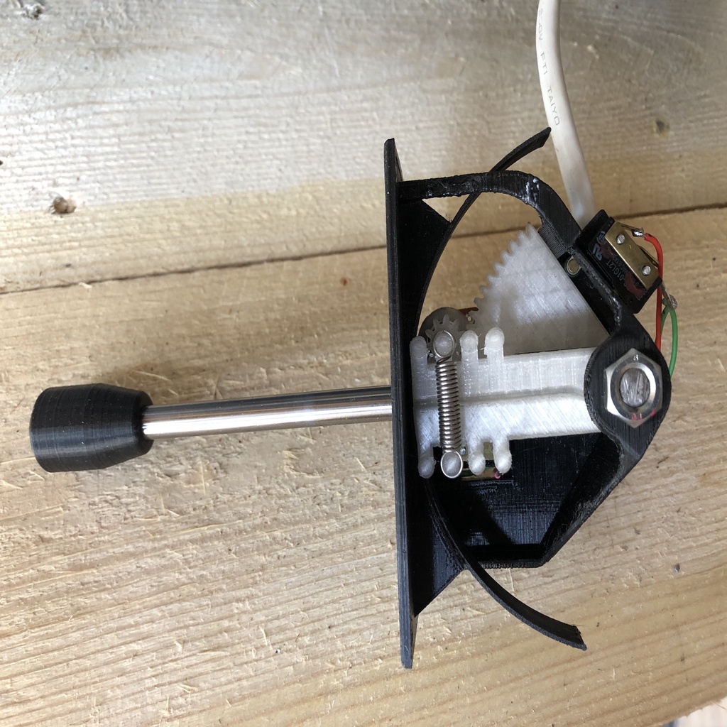
VFD direction/speed control lever mechanism
thingiverse
I wanted a lever control that controls both motor direction and speed/acceleration/deceleration like a hydraulic directional control valve on a screw press motor, using a variable speed drive. This mechanism is designed to trigger a VFD configured for 2-wire control mode for motor direction, and with an external potentiometer to control the motor speed: - 2x normally open microswitches (20mm x 10mm x 6mm body), one for forward, one for reverse rotation - 1x 16mm diameter linear potentiometer with a 6mm spline shaft At rest, the lever is in the center position, and the motor is stopped (both microswitches depressed). A spring holds the lever in the center/off position. When the lever is moved away from the center position, one microswitch is released, and the motor starts; the further the lever is moved away from center, the faster the motor runs (potentiometer is rotated as the lever is moved). As the lever is moved back toward the center position, the potentiometer is rotated back toward its start position, the motor slows down, and stops when the lever is returned to the center position. The potentiometer is returned to its start position, and the microswitch is depressed, breaking the run signal. If the lever is moved in the opposite side of center, the second microswitch is released, and the motor turns in the opposite direction. The mechanism rotates the same speed potentiometer regardless of which way the lever is moved: as the lever is moved away from center in either direction, the potentiometer is rotated clockwise. As the lever is moved toward center in either direction, the potentiometer is rotated counterclockwise. The hardware: - 8mm bolt for main axle and nut - A metal shaft for the lever: 8mm diameter x desired length. Knob end with 8mm thread x 10mm long, and other end with 6mm thread x 10mm long. - 2.5mm mounting screws and nuts for microswitches - M3 countersunk screws to mount assembly in the case - Extension spring with loops at either end as shown in photos: strength of spring according to user preference Before assembly, ream the 8mm holes on the following parts to ensure the holes are round and correct size: Chassis Potentiometer arm Shaft rod end Slot cover Spur gear Prior to assembly, refer to the 3D CAD images to see part orientations. To assemble: 1. First wire the "inner potentiometer and mount 2. Mount the "inner potentiometer to the chassis 3. Fit the potentiometer onto the potentiometer arm 4. Fit the potentiometer gear onto the potentiometer shaft 5. Fit the potentiometer arm into the chassis: rotate to maximize space for next step 6. Fit the spur gear: as you put this in, ensure that the potentiometer is rotated fully counterclockwise when the potentiometer arm and spur gear are seated against one another 7. Fit the lever shaft rod end 8. Fit the 8mm bolt through all of the above parts 9. Fit the spring to hold the arms together: there are four pairs of spring mounting points to enable adjustment of spring tension. 10. Slide the slot cover in between the chassis and inner mechanism, and align hole with hole between potentiometer arm and spur gear. Insert 6mm end of shaft through the slot in the chassis, slot cover, and screw into lever rod end. 11. Screw knob onto 8mm end of lever 12. Wire microswitches and potentiometer to VFD 13. Install assembly into case Note: As per photos, I did drill a hole in the side of the chassis to attach a "P-clip" using a M4 button head screw to strain relieve the control cable as shown in the photos
With this file you will be able to print VFD direction/speed control lever mechanism with your 3D printer. Click on the button and save the file on your computer to work, edit or customize your design. You can also find more 3D designs for printers on VFD direction/speed control lever mechanism.
