VaDiM by Solaris
prusaprinters
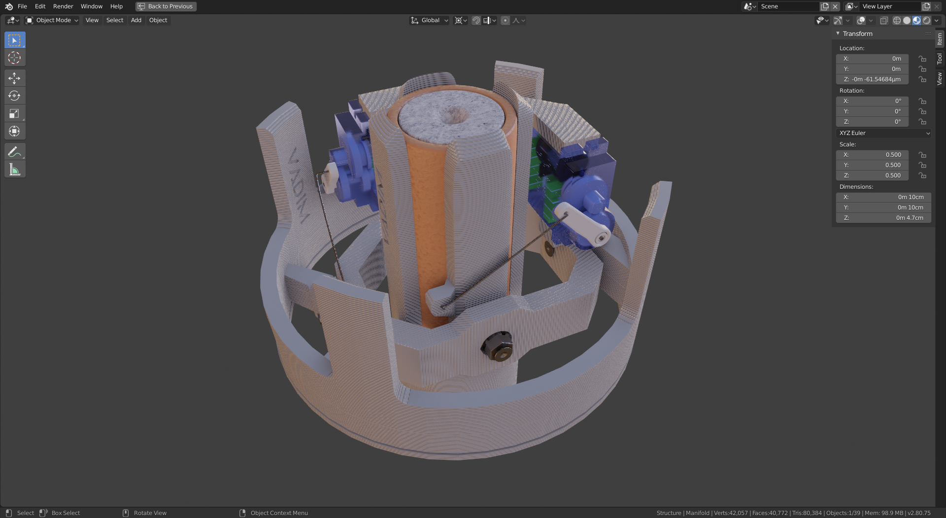
<p><strong>V</strong>ariable <strong>Di</strong>rection <strong>M</strong>ount<br/> F-class motor, ⌀=10cm , 1-to-1 transmission , NO supports!<br/> first module of our upcoming <em>SolarisOne</em> rocket</p> <p><strong>VaDiM</strong> stands for Variable Direction Mount<br/> (which is essentially a PR supername for Thrust Vector Control)</p> <p>It is a 3D printed mechanical unit that gets mounted on the inside of a model rocket fuselage (of 10cm diameter) and once paired with 2 servos, it can accurately and reliably¹ change the direction of a F-class (⌀=29mm) model rocket motor in order to achieve active stabilisation and control of the rocket.</p> <p>Structurally, the VaDiM module has 3 main components :</p> <blockquote><p><strong>Manifold</strong>, that connects the entire system to the rocket's fuselage,<br/> <strong>Outer</strong> gimbal, that contains 2 servos</p> <p><strong>Inner</strong> gimbal, which holds the rocket motor in a compliant² grip.<br/> The 2 gimbal axis pivot on a simple assembly of<br/> <strong> 4 bearings </strong> i⌀=3mm o⌀=10mm h=5mm<br/> 4 small screws,<br/> 8 nuts and 4 washers</p> </blockquote> <p>Functionally, it also requires the aforementioned<br/> <strong>2 9g servos</strong> and a discrete amount of .5mm steel wire to make the transmission linkages (a strong paperclip should do the trick)</p> <p>side note : the TRANSMISSION on VaDiM is <strong>1 TO 1</strong><br/> this gives you very high accuracy due to no cosine losses, but it requires that the transmission linkages are stronger, because there's more torque needed to rotate the gimbal</p> <p>Fully designed in the open-source 3D software "Blender", implementing a non-destructive workflow, heavily influenced by Chipp Walters' tutorials.</p> <p>One of the core design goals we've set from the very beginning is ensuring the parts can be successfully 3D-printed without the use of any support materials whatsoever.<br/> This ambitious goal crippled the first prototype of VaDiM because there was simply no way to make the servo mounts sturdy enough, as we could essentially only hold the from one side.</p> <p>The solution to this problem, however, came after a complete re-design of the outer gimbal.<br/> Instead of using the naive approach and printing the part vertically, we realized we could use any arbitrary plane as our printing plane.<br/> Upon this realisation, the solution presented itself: set a vertical 45° angle plane, perpendicular to the bisector of the 2 planes defined by the servos. This ensured the most printability over the critical region, enabling a complete shroud over the servos, holding them from 4 directions. This is the main breakthrough of the VaDiM system, as the outer gimbal is by far the most complex part out of the 3.</p> <hr/> <p>¹ remains to be determined<br/> ² okay :)) I'll admit that was a bit of a stretch</p> <h3>Print instructions</h3><p>takes about 10 hours to print. if you <em>really</em> have to save some time I'd suggest re-slicing the <strong>Manifold</strong> part with variable layer height, as you <del>definitely</del> need at least .2 to fit the bearings properly, but above that, you can go .35 if you don't mind the <em>VaDiM</em> text looking a bit janky. the <strong>inner</strong> is the simplest, so you should be able to get away with .35 everywhere except the very middle, where the M3 Hex nuts have to fit.<br/> I am very keen on efficiency and I'd recommend 30% infill at the very least ... any less than that and you're really pushing it</p> <p>please <em>don't</em> duck with the <strong>outer</strong> part, it's the most complex to print overall.</p> <p>In fact, I'd suggest printing it first because it has the highest chance of failing. Just to be safe, if you want to get it right the first time, it's a good idea to slow the printer speed as it's printing the bearing holes.</p> <p>once all parts are done you will need some M3 shafts. these are surprisingly difficult to find so, if you're like me, you'll end up just using m3 screws and some nuts to secure the bearings on the axel. the axel and bearing's inner roller must form a fixed subassemby, and the outer roller of the bearing is simply held in place by the holder's geometry (has it has a rim on the outside, so once assembled the bearings physically can't come out)<br/> I'd recommend not gluing the bearings in place, for the aforementioned reason, and so you can remove them without destroying the part if you want.</p> <p>quick side-note : the initial gcode has a .5 mm tolerance, so if your printer's in a nice warm, constant temperature spot it <em>should</em> print just fine, with the parts being essentially "peel and play", but, it's very likely this isn't going to be the case, so if the bearings don't fit, you'll need to sand down the inside of the holes. try to only scrape the edges and not damage the holding rim.</p> <p>After you've got your working gimbal, test-fit the servos, and drill a hole wherever the servo aligns with the part.</p> <p>you'll also need some steel wire to make the transmission linkages</p>
With this file you will be able to print VaDiM by Solaris with your 3D printer. Click on the button and save the file on your computer to work, edit or customize your design. You can also find more 3D designs for printers on VaDiM by Solaris.
