Vacuum Hose Swivel Cuff
prusaprinters
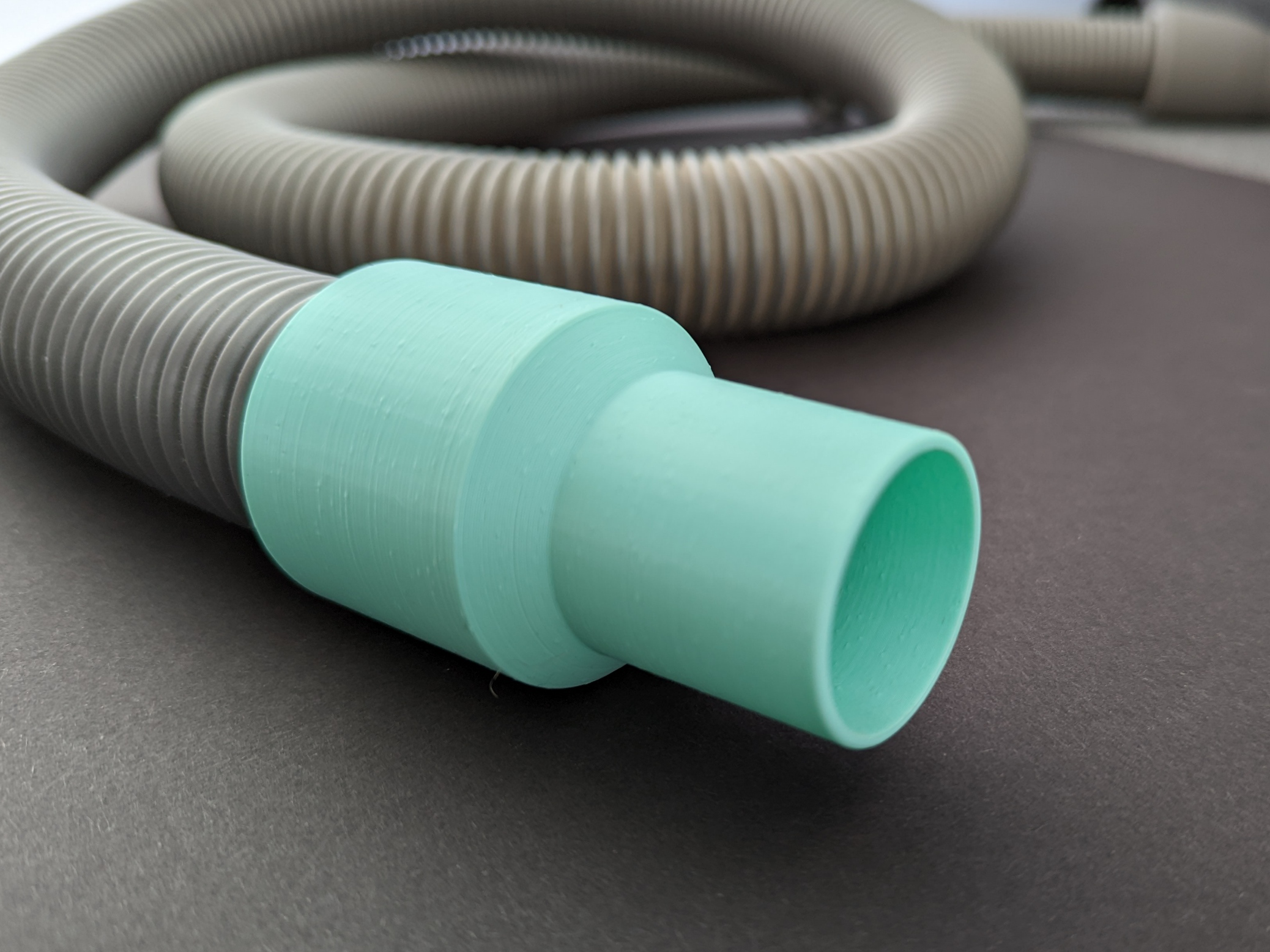
<h3>Preface</h3><p>I bought a Shop-Vac and Cyclone Dust separator a while ago; The Vacuum came with a 40mm hose, which is just not the best choice for a semi-static dust collector installation.<br>I ordered a 60mm hose and had to solve the problem of attaching it to the ports of the cyclone. The 50mm OD (outer diameter) ports would easily allow the use of some hose claps, but my installation is not that static, so here we are.</p><p>I initially designed a tapered 1-degree 50mm ID (inner diameter) to 60mm swivel cuff and was happy until I realized I'd need something to attach the cyclone's input to my table saw, sander, router, and similar. So I spent some time making my model parameterized.</p><figure class="image"><img src="https://media.printables.com/media/prints/277088/rich_content/03e2e539-285b-43fd-b8c4-09ffaff4c30c/3d-wireframe-perspective.png#%7B%22uuid%22%3A%22ff5b8206-a7a9-48e8-8d53-c6a003ceb484%22%2C%22w%22%3A800%2C%22h%22%3A600%7D"></figure><h3>Customizable Dimensions</h3><p>This model is the third iteration of my "research" in the realm of vacuum hose connectors. It seems to be standard for the business end of the hose to be the male connector with a one-degree taper and the nominal size describing the diameter at the tip. Even though my use case called for some specific shapes, I publish this model as a generic option or baseline for your remixes.</p><p>You will find the Fusion 360 file in the files section. To generate your custom part, get the following dimensions off your specific hose: <i>Outer Diameter</i>, <i>Inner Diameter</i>, <i>Spiral Pitch*</i>, and <i>Target Diameter</i>.</p><p>Open the <a href="https://www.autodesk.com/certification/learn/module/fusion360-intro-to-3d-modeling-associate-parametric-modeling-in-fusion-360:-sketching">Parameter Dialog</a> and adjust the values accordingly. <strong>Print the Screw/Nut part first</strong>, and do a test-fit. <strong>All other dimensions inherit from this one</strong>.</p><h3> </h3><p>* Pitch is the width of one rotation of the spiral. The distance from one bump to the next (start of one ridge to start of the next). When getting your values, count ten spirals and measure their distance, then divide this value by ten. This approach reduces the impact of unavoidable measurement errors.</p><h4> </h4><h4>Remarks</h4><p>Fusion 360 is sometimes a bit finicky about parameter changes. Try to change values in an order that allows meaningful interim results. E.g., when you increase the hose dimension, first increase OD, then ID.</p><p>If you go beyond simply changing values and design your own input/output shape, keep in mind that you don't want to have any steps in the draw direction. If possible, make the airflow as laminar as practical. Turbulence introduces drag, and sharp corners may as well introduce acoustic resonance.</p><h3> </h3><h3>Assembly Instruction </h3><p>Be advised that this design is nearly <strong>impossible to disassemble</strong> without breaking parts. If you plan to remove the swivel cuff, I suggest removing a section in the upper lip; then, you can pry out the retainer ring with a screwdriver. </p><h3> </h3><h3>Additionally Required Hardware</h3><p>None.</p><h3> </h3><h3>Print Instructions</h3><p>No support! Print all parts as oriented in their respective STL. The nut has a horizontal step as a solid stop for the hose. Add a per-model <strong>brim </strong>for additional bed adhesion. </p><p>Start with PrusaSlicer's <strong>default PETG 0.2mm</strong> presets and <strong>increase the perimeter count</strong> until the cross-section of the threaded part is all perimeter and no infill.</p>
With this file you will be able to print Vacuum Hose Swivel Cuff with your 3D printer. Click on the button and save the file on your computer to work, edit or customize your design. You can also find more 3D designs for printers on Vacuum Hose Swivel Cuff.