V1 Mid motor conversion for Tamiya MF-01X
prusaprinters
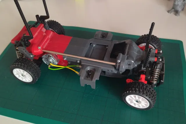
NOTE: This model is a prototype. I tried to catch as many issues as possible, the model works for me, but there might be other issues. Any feedback will be appreciated and found issues will be fixed in next version.New, improved version available!https://www.printables.com/model/712311-v2-mid-motor-conversion-for-tamiya-mf-01xAssembly manual is now available as pdf in files.This is little project that was in my mind since introduction of Tamiya's MF01X chassis. The chassis is versatile M-chassis, spiritual succesor of TL-01 with several flaws of the original fixed. But for some reason, Tamiya decided to put its motor high behind the rear axle, creating undesirable weight distribution (especially with light lipo batteries). Also, its gearing might be suitable for Jimny/Mercedes offroad models, but not really for rally Escort/Beetle ones. So, I decided to fix that.The design had three targets: it should support all standard wheelbase options (210, 225 and 239mm), it should look like a Tamiya part and use as few extra non-printed parts as possible. I also didn't want to include custom gears, as they add complexity to printing. Additional gears from Tamiya M-05 allowed me to cover gearing ranges of both TL-01 and Tamiya M-05 chassis.Parts needed for completion:1x Tamiya M-chassis gear set (50794 or 54277)1x 5x40mm gear shaft (13550027)2x 3x10mm M3 screw for motor mount2x 3x15mm M3 screw for internal gear holder1x 3x6mm M3 screw1x 3x6mm M3 countersunk screwthe rest of the screws is 10mm long - self tapping screws from the kit can be used, but may cause delamination - I used machine screws instead.2x 5x10x4 ball bearing1x 5x8x2.5 ball bearing - in case you use 54643 ball bearing set - replaces one flanged bearingPRINTINGI printed the parts on flat glass with 3mm brim. Textured print surfaces might introduce inaccuracy in height.Motor mount should be printed from ABS/ASA or atleast PETG. The rest can be printed from PETG or PLA+.The model is designed to be printed with 0.2mm layer height, 0.4mm nozzle and 3 perimeters. Lefthalf and Righthalf models include sacrificial bridges and supports to eliminate need for generated supports. However, height modifiers are needed to create 0.1mm gap between support and model:Righthalf:7.2-7.4 mm10.8-11 mm18-18.2 mmLefthalf:11.2-11.4mm20.4-20.6mm26.4-26.6mmI also added parts without supports and bridges.It is good idea to use modifiers to add perimeters in suspension mount area. This is a weak point of the design, it can withstand normal driving, but it will break in direct hit to the rear suspension arm.After printing, post processing will be needed to remove bridges. Redrilling screw holes to 2.6mm (threads) and 3mm for suspension arm mounts will be needed.Finally, the stock shaft needs to be shortened by 3mm - all you need is to drill new hole for the cross pin - bevel cover allows the excess part of the shaft poke through, so it doesn't need to be cut. Of course, all wheelbase options are supported, with same spacers as the kit.Update 22/11/14 - added chassis models without supportsUpdate 23/2/1 - added assembly manual
With this file you will be able to print V1 Mid motor conversion for Tamiya MF-01X with your 3D printer. Click on the button and save the file on your computer to work, edit or customize your design. You can also find more 3D designs for printers on V1 Mid motor conversion for Tamiya MF-01X.