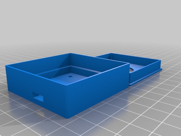
Ublox GPS Module Case
thingiverse
This is a compact housing that I built around a Ublox NEO-6M GPS receiver based on the one sold by Unmanned Tech in the UK. Update 11/08/2014: Some extra space was added to the parts so that minor over-printing issues wouldn't keep the lid from attaching properly. The option is now available to create four mounting holes in the base for securing a quadcopter. Additionally, a configurable tolerance parameter has been introduced which adds space between the lid and base, and also between the base and the printed circuit board (PCB). This parameter can be adjusted by editing the source code of the case, but I have set the default quite tightly. The most recent snapshot is available on GitHub for all to see. Instructions This is a compact housing that I built around a Ublox NEO-6M GPS receiver based on the one sold by Unmanned Tech in the UK. Update 11/08/2014: Some extra space was added to the parts so that minor over-printing issues wouldn't keep the lid from attaching properly. The option is now available to create four mounting holes in the base for securing a quadcopter. Additionally, a configurable tolerance parameter has been introduced which adds space between the lid and base, and also between the base and the printed circuit board (PCB). This parameter can be adjusted by editing the source code of the case, but I have set the default quite tightly. The most recent snapshot is available on GitHub for all to see. Print out two parts that make up the base and the lid using any standard 3D printing techniques. I expect my preset settings should be sufficient for a standard version two GPS module although please feel free to tighten them if required. Using the configurator on this page, or by modifying the scad source code directly, you can quickly modify many different parameters to suit your specific needs and preferences including: The width of the printed circuit board that the Ublox NEO-6M module resides upon. Note, it's assumed that this PCB will be a square; if not please put in its lengthiest dimension. Clearance above and below the GPS receiver that components sit in. Width and Position. How far away is your cable connector from the edge of your GPS case. Where you want to make your mounting holes to fit your screws for securing it onto an airplane frame (Quadcopter). The distance between two points; how large you'd like those mounts to be for holding it in place firmly with one bolt size specified here as diameter instead where set zero not needed because there will then never any drilled through metal at bottom surface so they're removable without further modifications required afterwards afterwards. Wall height - wall depth both sides which gives better stability also add more strength overall especially considering added corners' curves radius also make PCB thinner or even make windows smaller by entering specific measurements underneath respectively shown below: corner rounding affects final product visual appeal quite significantly too, thus altering radius from current number would dramatically impact look making significant noticeable changes last but certainly not least we also see parameter labeled Tolerance this distance adds more room giving slightly more flexibility around certain components located closest edge board while ensuring good airflow passage still maintaining optimal weight balance everywhere.
With this file you will be able to print Ublox GPS Module Case with your 3D printer. Click on the button and save the file on your computer to work, edit or customize your design. You can also find more 3D designs for printers on Ublox GPS Module Case.
