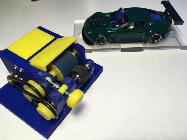
Tyre Truer MKIII for slot cars 1/32
prusaprinters
It all started with the idea to push the limits of the 3D printing to create a precision tool that I could have made out of metal instead. The first version was without real bearings so after a while the main bearing started to get clearance but I had proved myself that it could be possible to create a tool to be used for the slot car hobby with repetitive and reasonable results. This is the evolution of the first tyre truer I designed and printed few month ago. Few useful features have been added such as: the use of three bearings 626-2Z (6x19x6 mm) which will give stability to the grinding spindle new grinding wheel with double support possibility to connect the vacuum cleaner tube (an adapter for a 35 mm hose is included) the separation wall between the motor and the grinding wheel motor cover grinding wheel protection electrical switch conduit for electrical cables ventilation for the driving motor etc. etc. Updates V01 main body (changed the fulcrum of the swing arm) main and secondary pulleys (easier alignement) added the new grinding wheel + axial spacers (tested the wheel and it works very fine) added the electrical cable clamp added the vacuum adapter to fit my Dyson's 35mm ID Updates V02 improved clearances based on the 3D printed parts common size for all steel shafts, now all dia. 6 mm except the tyre spindle (3/32") Updates V03 I added Gv-013_1 grinding wheel drum V03 since some users experienced some errors on the V02 file of the drum Cheers, JamieG Print Settings Printer: Velleman Vertex K8400 Rafts: Yes Supports: No Resolution: 0,20 Infill: 20% Notes: The first parts I printed were the body and the spindle holder to make sure the printed parts fit together with the correct clearances. I am not sure my printer is perfectly calibrated so please let me know if you find excessive clearance between the two main parts. All the remaining bits and pieces are quite fast to print and could be printed in one lot but I preferred to print them individually to avoid much jumping from one component to the other during the printing process with possible lower quality of the final print. Printing time approx 6-7h (main body 4 h 30 min) Post-Printing Required hardware The hardware you need is the following: 3 bearings 6x19x6 mm 626-2Z 1 grounded steel shaft dia. 6 mm, 78 mm length 1 grounded steel shaft dia. 6 mm, 68 mm length 1 grounded steel shaft dia. 3/32", 76 mm length 3 grub screws M3 x 6 mm 1 grub screw M3 x 3 mm for the motor pulley* (see note) 1 screw M3 40 mm long here you need to file and fiddle a little (the best is if you have a lathe to shape the hear down to 4 mm so it fits into the recess of the pivot shaft) 4 M3 nuts to lock the knob (1 is inserted - after warming up the nut - into the knob; the other two are needed as a stopper to regulate the depth of the grinding on the wheel and most importantly to be able to help holding still the screw while inserting the knob) 3 standard slot car bronze bushings (I have quite few slot.it and NSR -nsrslot.it- bushings but you have to file away one flange since they are double flanged - here again a small lathe is helpful) 4 M3 self tapping screws to connect the covers 2 M2 screws approx 10 mm long (I changed the thread to M3) with washers to connect the motor to the main body 1 electric DC motor (i.e. DC 6V-12V 6500RPM Large Torque JOHNSON 385 Motor Carbon Brush DC Motor for Tools - http://www.ebay.com/itm/262443105339?_trksid=p2057872.m2749.l2649&ssPageName=STRK%3AMEBIDX%3AIT) 1 on-off switch to be press fitted into the slot of the main body (I don't remember where i bought it - dimensions 17,5x12,5 mm approx) 1 electrical cables suitable for the application (I used some redundant cables with crocodile clips already installed) And off course a Drum Sanding Sleeve of 25 mm (they have standard grit) (*) I had already a motor with installed the previously made brass pulley. I am not entirely sure the plastic PLA will have a long life since the motor shaft is getting quite hot!!! Tools Since this tools is meant to have a good precision, it is recommended the use of reamers. With the latest design I standardized all metal shafts to dia. 6 mm to limit the number of tools required. There is the need of a dia. 4,9 mm drill bit (sharp) to ream the hole where the bushings for the tyre spindle will sit. You will need also different sizes of drill bits to refine all the holes present in the different parts. I discourage the use of electric tools, use only hand tools to get a better feeling and precision. An M3 tap is also required to shape all threads. Use a drill bit dia. 2 to refine the hole before threading. For the boring of bearings seats (dia. 19mm) I was lucky I had a 19 mm drill so I carefully redressed by hand the seats. If you don't have it, then you have to make sure the refine the seats that the bearings can be pressed in with a slightly tight fit. The remaining tools are the usual ones, files, sand paper, screw drivers, soldering iron, etc. Assembly Connect the spindle holder to the main body inserting the 68 mm long shaft. Insert the pivot pin #1 into the main body with the hole accessible since next thing you have to fiddle a little inserting the M3 40mm long screw. the modified head should fit completely into the recess. Next insert the pivot pin #2 into the spindle holder making sure it is aligned with the screw. first add a couple of M3 nuts and tight them together toward the upper extremity so you have something to hold the screw when inserting it into the pivot pin #2 and later when you will add an extra nut and the knob. Press fit the bearings by hand or with the help of a bench clamp with soft jaws being extremely careful to not apply pressure to the inner bearings. the press fit should be enough to keep them in place but they might be glued into place (some loctite-ish 648 could be applied but I haven't tested the compatibility with the PLA yet) Insert the 78 mm long shaft into the bearings, one spacer, grinding wheel with the sanding roll and then the next spacer. Here it can be tricky since the grounded shafts can be very tight on the bearings. Do not hammer them into the bearings because you will damage them. Get some sand paper and reduce the diameter, usually it can be just 100 of a millimeter. The shaft should slide with a light fit, no clearance must be present between the shaft and inner bearing. After you have successfully inserted the grinding wheel into position it is time to slightly move aside the sanding roll to be able to access the locking grub screw. Do not tighten the grub screw too hard, here or in any other component. Set the sanding roll back in position. Insert the motor into the body, plug in the switch and solder the cables. The motor is quite tight so you have to fiddle a little with it but there is enough space to insert it even with the pulley installed. Insert the tyre spindle bushing with the 76 mm long shaft dia 3/32" without inserting them into the seats and then superglue the bushings into the spindle holder seats making sure the shaft rotate freely = no misalignment. Add the covers and the remaining pulleys and you are ready to install the tyre to be grinded to size. You will need a couple of aluminium retainers with grub screw to avoid the tyre spindle is moving sideways. The best is to have a couple from the usual specialized suppliers of slot cars. Grinding process It is recommended to glue the tyres to the hub but this you should know it already. Do not use excessive force between the spindle and the grinding wheel. First you will unnecessary heat up the revolving parts, damage the motor and spoil a set of new tyres. Apply a step by step procedure, let it grind until you feel that there no more pressure and the motor is spinning freely. Stop and check time to time to see the result and possibly measure the diameter of tyre. When you are almost finished with the first tyre, set the two nuts to have them into position as a stopper toward the pivot pin #2 so you can replicated the second tyre with precision. Take the final extra pass on the first tyre and you are ready to move to the next one. PS: don't forget to round the tyre's edges while you are at it and you can refine the texture of the tyre with same fine sandpaper (the sanding rolls comes with maybe a too rough grain - probably 120). I have done few tests and the results have been very good. I have also tested two wheels at the same time but I would not recommend it except for roughing them initially. I don't like to work on the side of the grinding wheel since the underneath grub screw that could have caused some tiny distortion of the grinding wheel. Have fun and drive carefully ;-) Category: Tools
With this file you will be able to print Tyre Truer MKIII for slot cars 1/32 with your 3D printer. Click on the button and save the file on your computer to work, edit or customize your design. You can also find more 3D designs for printers on Tyre Truer MKIII for slot cars 1/32.