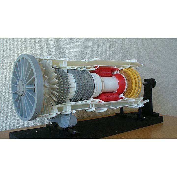
Turbofan Engine, Low Bypass, Full Ducted, 1960s
myminifactory
In the 1960s, short- and medium-range jet airliners such as the B727, B737, and DC-9 appeared, contributing greatly to the shift to jets.They were powered by the P&W JT-8D turbofan engine. It became a best-selling engine after that, with over 14,000 units produced, including advanced versions. Although the bypass ratio was only about 1:1, it made the most of the technology available at the time.Structurally, assembly work was required, with ring-sliced parts stacked one by one.This is a reference model to learn about the rough structural characteristics of the model. Some flanges have been integrated for model assembly, and the stator vanes have been omitted to make the air flow path easier to understand. A. Main Structural Features of this model ① Full ducted cases - 6, 8, 13 stage extraction ducts are reproduced ② Low pressure compressor - 2 stage fan + 4 stage axial compressor For the detail structure of the fans, please refer to my model below Jet-engine-component-fan-metal-blade-with-snubber (JEC-07-1) Jet-engine-component-fan-metal-blade-pin-rivet-type (JEC-07-2) ③ High pressure compressor - 7 stage axial compressor ④ Combustor - 9 can annular type ⑤ High pressure turbine - single stage axial turbine with shroud ⑥ Low pressure turbine - 3 stage axial turbine with shroud ⑦ Can be disassembled and assembled ⑧ Thumb turning tool included only for low pressure spool B. Assembly Manual (PDF format, total 17 pages)The detail assembly manual including "Parts-List", "After printing treatment" and "Assembly procedure" are prepared based on "Standard Skill (Filing, Drilling, Tapping and painting)". C. Download files includes; - files: STL Files (51 items) STL file name: "ws" of last 2 digits means "With Support" which special designed. D. Purchase Parts Information; - Aluminum Tubes - φ5, 7, 10 - Screws - M1.4x3.5L, M1.4x6L, M2x18L Micro screws M1.4 - Direct screw-in to 1 mm dia hole (No nut). But if you have the M1.4 Tap, it will be very useful. - Aluminum Tubes - φ5, 7, 10 E. Total Net Print Time: Approx. 100HR - (Estimated as case of PLA, 0.4mm Nozzle, 0.2mm Layer Height, 40% infill and No raft and support) Note: When at actual print, each parameter may be adjusted by your experience. F. 3D printing settings Raft, Support, Layer Height, Infill: Depending on your experience. But the parts having blade/vane, small shaft and thin portion: 100% infill is recommended. My models were printed by "idbox" using with 0.4 nozzle, 1.75 PLA. I do hope your success!!
With this file you will be able to print Turbofan Engine, Low Bypass, Full Ducted, 1960s with your 3D printer. Click on the button and save the file on your computer to work, edit or customize your design. You can also find more 3D designs for printers on Turbofan Engine, Low Bypass, Full Ducted, 1960s.
