Trunk lid pull down gearbox for 1985-1999 Cadillac deVille
prusaprinters
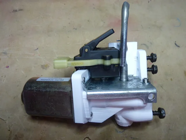
This Thing is a replacement for the main gearbox body for the trunk lid pull-down assembly in my 1992 Cadillac deVille, reverse-engineered from the original part (as mine broke in several places, due to age and excessive mechanical stress). It supposedly fits other deVilles from 1985 to 1999, and may fit some other makes and models also (I am not entirely sure). This is just the gearbox casing, with the motor cover separated-out into a bolt-on unit (you can see the broken-and-reglued original part at the end of the photo list), so you will need several of the original parts to make use of these files: the motor and brush assembly the little black corner piece that goes behind the brush assembly's connector tabs the little cap from the end of the motor rotor spindle (its a simple sleeve/sliding bearing; you'll have to press it out of the original part with a small screwdriver) the pull-down loop assembly with thrust bearing, lifter gear, and spring washer the limiter switch assembly The three large main mounting screws. You can re-use all of the original screws to put this together (four new screws will still be needed), but I designed this so that proper machine screws and nuts can be used instead, as I dislike screws just biting into plastic to hold things together (especially on 3d-printed parts) if there's another way. Theoretically, the brush assembly, lifting gear, that little black corner piece, and most of the limiter switch assembly could also be replaced with 3d-printed parts, but mine were in good shape, so I re-used them. I do not plan to create models for these. Update 2018-08-02: My part split along layer lines because it was printed too cold and with too much fan. After seeing where it split, here's a new version (specifically, of the gearbox part) with thicker walls around the motor spindle, and slightly larger holes for the main mounting screws. Print instructionsSupports: Yes Resolution: 0.2 mm Infill: 80-100% Notes: This part needs to be strong, so print slow, hot as hell, and with as little fan as you can get away with, and use very thick skin/walls (4 mm should do). Basically, you want the part to be solid or nearly so. Make your interior lines (skin, walls, infill) as wide as your hotend can reliably do. Since this will go in a car, do not use PLA - it won't stand the summer heat. I printed mine in PETG (Atomic Bright White), since it's rigid enough and temperature-tolerant. I do not know what other plastics will work here. Incidentally, the original part appears to be made of polycarbonate. Post-Printing In addition to the supports added by your slicer, the gear box has a ring and a set of little vanes about a centimeter tall at the bottom end, just there for the purposes of bed adhesion. Cut them off if so desired - they shouldn't get in the way if you don't, but serve no purpose once the part's in the car. How I Designed This Blender, with lots of measuring and low-density test prints. Custom Section Assembly Take everything apart and clean all of the re-usable parts thoroughly, then assemble the lifting gear, its thrust bearing, and its spring washer onto the pull-down loop/bracket, re-lubing all geared or sliding surfaces in the process (I use Super Lube #51004, but I suppose even 3-in-1 oil will do if that's all you have, just so long as it's plastic-safe). Make sure the pull-down loop is about half way extended on its screw/worm, and use two M4 x 24 mm screws, with washers and nuts to mount it to the gear box, taking care to align the stud in the corner with its cut in the bracket. Rotate the loop so that the two tabs stick out toward the motor mount. Note that one of the two holes has a little bit covering it on the bottom (a little support for the bottom side of the mounting stud). Just cut it off, it'll get in the way of the nut. Press three M3 nuts into their traps in the motor cover. Carefully slide the brush assembly onto the motor, using a knife to press the brushes in enough to get past the edge of the rotor's commutator. Take care to put it in the right way, with its flatter side facing outward, and its connector wires next to the larger of motor's two mounting tabs. Press the motor cover into place carefully, taking care to align the brush assembly's two triangular tabs with the corresponding cuts in the motor cover. You may have to reach in with a knife or small screwdriver and press sideways or inward to align the tabs. Make sure the connector tabs and wires fit into their cutout in the cover properly. Using a knife, carefully lift the corner of the motor cover away from the motor, at the larger of the two mounting tabs, and snap the little black cover piece into place over its mounting stud. Careful, don't break the stud. This little cover piece only goes in one way (the double-tapered end points away from the motor, with the side with the three little nubs sticking into the cover, triangular locking tabs facing outward). Carefully press the cover back on, making sure everything is still aligned, check that you can spin the rotor (it's a little tight, but not excessively-so), and secure the cover to the motor with two M3 x 14 mm screws and nuts. Place the little cap over the end of the rotor spindle. Slide the motor/spindle into its receptacle in the side of the gearbox, and press it in all the way (seating the little cap into place in the process), then mount the motor/cover to the gear box with three M3 x 8 mm screws, one M3 x 18-20 mm screw, and nuts. The tab on the side of the motor cover takes the longer screw, which will have to be inserted from the motor side of the mount rather than the gearbox side. On the limiter switch assembly, there's a small tab that fits into a receiver slot in the upper mount on the gear box, and a small hook just opposite it that slides into another slot on the other side of the upper mount. On the top of the switch assembly is a large paddle switch, and just below that, sticking out one side, is a small snap-action toggle switch. On the bottom is a small two-pin connector molded into the body of the switch, pointing down, with a 4-pin connector just above it pointing sideways. Insert the switch assembly's tab into the wider part of the receiver slot in the gear box, taking care to put the small toggle switch between the pull-down loop's two tabs. Hold the switch assembly flat against the upper mount, and slide it down so that the tab goes into the narrow, locking part of the receiver slot, with the hook engaging the slot on the other side. Carefully press the switch assembly's 2-pin connector onto its mate in the motor cover, engaging the locking tab on that little black piece. Use an M3 x 40-50 mm screw, with washers and nut, to secure the switch assembly via its hole in the gear box upper mount. The three large mounting screws are the self-tapping type - at least, the ones in my car are. To reduce the risk of cracking and ruining your new part, use one of them as you would a thread tap, by carefully driving it part way in, removing it, clearing any debris, and repeating, lining it up with the threads' cuts each time. You can now install it in the car.
With this file you will be able to print Trunk lid pull down gearbox for 1985-1999 Cadillac deVille with your 3D printer. Click on the button and save the file on your computer to work, edit or customize your design. You can also find more 3D designs for printers on Trunk lid pull down gearbox for 1985-1999 Cadillac deVille.