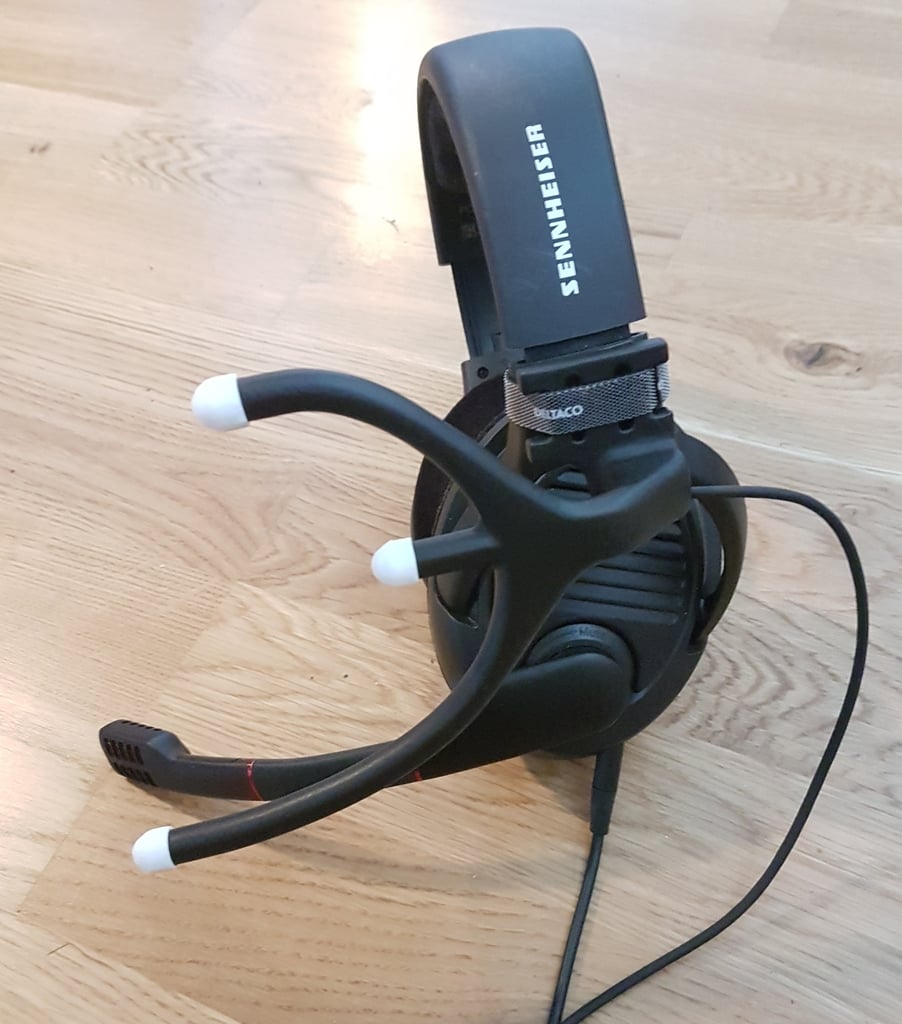
TrackIR LED holder
thingiverse
NOTICE: It is strictly prohibited to manufacture and sell this design on eBay or any other platform. This restriction applies even if modifications are made to the original design. Please thoroughly review the licensing agreement. I required a more advanced LED holder, so I designed my own. To clarify, this design is compatible with TrackIR as well as OpenTrack and similar software. Parts needed: 3 IR LEDs 1 resistor (or combine two in parallel if you cannot find an exact match) 1 PTC fuse with a minimum rating of 300mA (I used 300mA for my setup) 4 thin wires (26 AWG) labeled cables 1-4 in the instructions 1 thin steel wire approximately 20cm long 1 DC-power source with a cable or USB cable 1 velcro strip Using the LED Series Array Wizard, I discovered that three LEDs (Vf = 1.2-1.4 V, If = 100mA) connected in series and powered by 5 VDC require an 8.2 ohm resistor. I utilized a parallel resistor calculator to determine that combining two resistors, one with a value of 10 ohms and the other with a value of 47 ohms, results in almost exactly 8.2 ohms. A PTC fuse rated at 300mA is used to protect the power source (either a separate PSU or the motherboard if using USB for power). I based my setup on the schematics provided by this link and adapted it with different components: http://myfreetrackheadset.blogspot.com/. Step 1. Pass the steel wire through the bottom LED opening, all the way through the frame until it emerges from the back. Step 2. Bend the wire and attach cables 3 and 4, then pull them through the frame. Ensure that at least 5cm of cable is left to prevent it from being pulled into the frame when connecting with other cables. Step 3. Repeat steps 1 and 2, but this time through the top LED opening and using cables 1 and 2. Step 4. Pass the steel wire through the middle LED opening. Step 5. Attach the ends of cables 2 and 3 and pull them through the frame. Step 6. Solder the LEDs, taking note of the polarity and connecting them in series. I used shrink tube to protect the pins from shorting. Step 7. Insert the LEDs into the frame and carefully pull on cables 1 and 4 to remove excess cable within the frame. Step 8. Solder the resistor and fuse onto the positive cable. Step 9. Insert the power source cable through the pull release holes in the frame. Step 10. Solder the power cable to cables 1 and 4, taking note of the polarity. Step 11. Push excess cable, resistor, and fuse into the frame. Step 12. Test the LEDs using a mobile phone camera. If you have purchased narrow-angle LEDs like me, you may need to use omni bouncers. EDIT: I added a small component for a switch. It can be a bit tricky to fit everything in place, but it is doable. I also included pictures demonstrating how to assemble the design.
With this file you will be able to print TrackIR LED holder with your 3D printer. Click on the button and save the file on your computer to work, edit or customize your design. You can also find more 3D designs for printers on TrackIR LED holder.
