Top Fan for PrusaBox by PrinterBox
prusaprinters
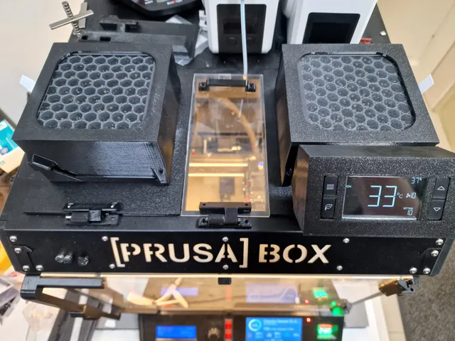
For this design, I disassembled an AC Infinity T8 and created a top exhaust for the PrusaBox out of its parts. It is essentially based on my first design.If you don't have an AC Infinity T8 or don't want to spent 120 bucks on one just to disassemble it, check out this simpler and cheaper version:https://www.printables.com/de/model/227651-top-fan-enclosure-with-hepa-carbon-filter-for-prusIf you want to rip apart a T8, this is what you get in the end: A few words beforehand printing and building. The AC Infintiy's fans are quiet (at ~35 db), compared to the Noctua Industrial for example. But they also have less pressure.Here's a comparison. As you can see the Noctua is able to push around 1.33 m/s through the HEPA and Carbon filter Even though Infinity fans builds deeper (36 mm) than the Noctua's 25mm they are no competitors to the Noctua. The Noctua compensates it's smaller height with speed, but also with extreme noise. That's the reason I've designed two exhausts for both T8 fans. Together they achieve more throughput than one Noctua and are still quieter in stereo.Want to do this? Okay. Let's get started.It is important that you follow the assembly order. Otherwise you will run into troubles.Download & Printing Instruction Either download the file: "Filter-Infinity-All-Parts-Right-V22.stl" and "Filter-Infinity-All-Parts-Left-V22" (if you want to have the left fan too) and split the parts with the split function of your slicerOR download Mandatory: Filter-Infinity-Part1-Right-V22.stlFilter-Infinity-Part2-Right-V22.stlFilter-Infinity-Part3-Right-V22.stlFilter-Infinity-Part4-Right-V22.stlFilter-Infinity-Part5-Right-V22.stl Optional Filter-Infinity-Part1-Left-V22.stlFilter-Infinity-Part2-Left-V22.stlFilter-Infinity-Part3-Left-V22.stlFilter-Infinity-Part4-Left-V22.stl Some parts need support. Look at the gcode. Parts needed You need an AC Infinity AIRTITAN T8-N (AC-ATT8-N)https://acinfinity.com/home-ventilation/crawl-space-basement-fans/airtitan-t8-n-crawl-space-and-basement-ventilator-fan-temperature-and-humidity-controller-ip-44-rated-intake/ You need 1x HEPA and 1x carbon filter per fan.. You need several 3 mm square nuts and 3 mm screws of different lengths. The longest screw you need has a length of 50 mm. You need a 4-pin PWM extension cable. You need jumper wires. Female-to-male Step 1 Grab your T8 and tear it apart. Be patient when removing the hotglue. Use a plier and peel it off bit by bit. You did it. Step 2 Assembly of fan housingInstall the fan into the housing. Make sure that the fan is blowing into the right direction. The arrow on the side of the fan has to point into the direction of the filters. Guide the cable through the opening on the side. Be careful not to squeeze the cable. Do not mount it to the base plate until I tell you to do so … Step 3 Print base, cable tower and hinge. Be very accurate in removing the remains of the support from the edge. Otherwise the top door won't close properly. Take a knife or a sanding block if necessary.Hint: I recomend to print the base plate with PETG. The reason is it's more flexible than PLA and there's less risk to break the cable holders.Hint: Don't remove the print from the printer until the base plate has cooled down. It's the best chance for it to stay straight and do not bend while cooling.Mount cable tower and hinge to the base plate.It's crucial that the screws for the hinge are completely even with the base plate. Important: Use very short M3 screws. Make sure that they do not stick out at the top, otherwise you will not be able to mount the cable tower. There is only a small gap between hinge and cable tower. This is too long In the end is should look like this. Step 4 Be brave and cut the power cable of the original power supply that comes with the AC infinity T8 (talk to your therapist, if necessary) and strip the insulation on both ends. Step 5 Print the square tunnel and guide the cable of the fan through.Next guide the cable through the hole on the back of the cable tower. The cable of the probe and the power cable goes through the plate into the cable towerStep 5a If you want to install the second fan of the Infinity, add an 60cm 4-pin connector extension cable, like the Noctua NA-SEC3 or something cheaper.This end goes into the cable tower. Step 6 Print the housing for the electronics. Step 7 Add the square nuts to the display cover. This is by far the most sucking part. You gonna hate me. I know for sure. It's not easy to get them in, but it can be done. I believe in you!Make sure the nuts are aligned with the holes. This is the best way to get them in by the way. Guide and hold them with an allen key. Then press them in with the side of a plier. Use the tip of a screw to press the nut a little more, far enough to grab and align them with an allen key. That should do the trick.Step 8Pre-drill all holes with a screw. It will makes things a lot easier later on. Believe me. Don't be lazy. Step 9 Mount the board with the input jacks. Use the original screws. Plug in the power cable and the cable of the probe. Mount everthing to the cable tower. You will notice that theres is a bit of resistance when mounting the display base to the cable tower. This is because the connector of the power cable is a too long. Try to bend the power cable a bit. Be careful not to damage the input jack for the power connector. Your'e done Step 10 Insert the the window, followed by the plastic frame with the knobs and then mount the controller board. Use the orignal screws.Connect the wire for the input jacks and the fan. Step 10aIf you also want to use the second fan, you run into a problem. You will be able to connect the extension cable to the fan connector, but it's not possible to connect the other end of the extension cable to the connector of the board. The connector of the extension cable is simply too big.But rescue is near. Use jumper wires. Take short ones. Plug the pin ends of the jumper wires to the extension cable. But make sure not to cross cables/connections.Step 11 It would be a good idea now to connect all the stuff provisionally and test it. Oh shoot! We've cut the power cable. Damn it! Call your therapist (again) immediately.No problem. Use Wago connectors Step 12 Now mount the display. It's a bit tricky to reach the screws, but I figured out this is the best way to do it. Now you know why I told you not to install the fan housing. If you had (you haven't, right?), you wouldn't be able to reach the screws now. ;)Step 13 Remember that guy? Plug 'em in. Step 14 Now you have to decide wether you want to use the Push Back Blocker or not. Since the fan will have a hard time trying to push air trough the filters, some (most) of the air won't make it and will be pushed back into the enclosure. That's normal. But if you fear this could affect your print, you can install the - what I call - "Push Back Blocker".Warning: Do not use the Push Back Blocker if you print parts that need the entire height of the printer. The filament may stick to the edge of it. You have to print the three large spacers and get some 50 x m3 screws.If you have troubles to get the spacer into the holes of the blocker, simply widen them a bit with the tip of knife. For the other end of the spacers, you may need a little force to plug them into the holes of the base plate. It's a little tight. Step 15Whatever you decided, you can finally screw the fan onto the base plate and you're done. Congrats! Step 16Now print the second fan housing for the left fan, in case you want to. I do not explain how to assemble it, since this is exactly the same - only simpler ;) The only thing to mention is, that there's hole to get the fan cable through.Step 17It's time for marriage. Put both fans in. Connect the extension cable runing out of the right fan to the connector of the left fan. Either you drill a hole for the power cable into back of the printer enclosure (which I did) or you use the Buck Converter Box to go in. Connect both ends of the power cable with Wago connectors or solder it. Step 18Do some cable management. Browse around in my designs. I have lots of cable ducts to offer, that allows you to hide the power cable and the cable of the probe. Step 19 Now you have this wonderful gap, hm? Either you are brave enough to cut the original top window or you are a wimp and buy a piece of plexiglas. Cut it, like I did! T-a-k-e y-o-u-r t-i-m-e with the knife. Do not use too much force/pressure (plexiglas is breaking easily).I had to pull the blade around thirty times. If you were successful, sand the edge and test it Step 20 Print the original hinge and handle. You'll find it in the download section on the printer box website.https://help.printer-box.com/home/download/ Step 21 Use superglue to fix hinge and handle and a 3 mm screw to connect both hinge parts. The EndYou have to watch the fourth episode of “Stranger Things” now or at least eat some gummi bears and give yourself a stereo blast from your two fans.
With this file you will be able to print Top Fan for PrusaBox by PrinterBox with your 3D printer. Click on the button and save the file on your computer to work, edit or customize your design. You can also find more 3D designs for printers on Top Fan for PrusaBox by PrinterBox.