Tilt Feet for Electronics Enclosure
prusaprinters
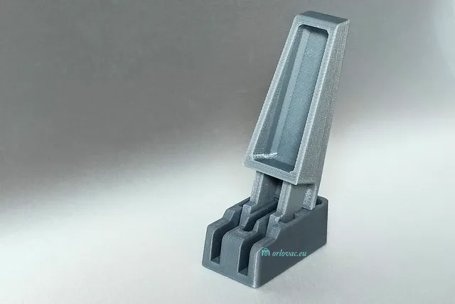
Some electronics devices with display and adjustment buttons are quite impractical to have standing horisontally on the table. To solve this problem you need tilt feet printed and mounted on you enclosure. When I assembled my RD6018W Power Supply, it was obvious an impracticality. Printed details: Here we have three different details for print: a Foot, a Leg and a Hole Template. The hole template is an optional detail which I suggest to print it, only one piece. It helps to trim two ‘rubber’ pins placed in every foot part to an equal length and kan be also used to mark drill holes in a chassis too. Only the leg has a tiny amount of print support material already generated in existing sliced files. When printed, remove this support by help of pliers and clean more with scalpel if it is needed. For a complete enclosure, you need to print: Foot, 4 pcs and Leg, 2 pcs. I have generated sliced files with 0.15mm layer and PLA material, which makes a very nice result. For a fine result you will consume time and when we owe a 3D printer it doesn't matter. These tilt feet is hard to find and if you find them, you have to wait for package to arrive. Under that time you can print your own things. In generated layer height, I get nice locking of the leg both in open and closed positions. These ‘rubber’ pins are erasers from a permanent pens, type Faber-Castell permanent Multimark 1513F or simillar. The eraser does not have any use todey. They where used when we used permanet pens to write on overheadfilms. When used in this design, it prevents slippery feet. Nice to reuse something which will be thrown in the trash anyway. If you do not have such pens, another option may be 7 mm glue sticks for glue gun. Just trim length as described above. Assembly instruction: The Figure 1. shows how to insert a leg into a foot, by pressing the leg firmly into the foot keeping it near perpendicular to the surface of the table. Pay attention to the orientation, see Figure 2. Incorrectly inserted leg is hard or impossible to remove. When the leg is inserted move it back and forth, i. e. open and close it. In two outer holes press in an eraser divided into two parts or place a complete eraser piece in one hole, use the hole template and cut off excess, place the rest in the another hole and again cut off the excess, see Figure 3, (where you can find a table with Bill of Materials). Now you will get two 'rubber' feet pins of equal length installed in each foot. Use the hole template to drill two holes for each foot in the chassis (remember correct orientation) or perform distance measurement between these holes, which need to be 25 mm, and DIA of 3 to 3.5 mm, for two M3 screws, length of 8 - 10 mm. For all feet, totally 8 screws are needed. The screws will make its own threads into the foot. When all feet are mounted (see provided pictures), you can have your device horisontaly placed on the table or tilted upwards toward your face, for better visibility. Now, my Power Supply's display is much more convinient to look at and read it. The construction is enough robust to support a box with weight more than 10 kg.
With this file you will be able to print Tilt Feet for Electronics Enclosure with your 3D printer. Click on the button and save the file on your computer to work, edit or customize your design. You can also find more 3D designs for printers on Tilt Feet for Electronics Enclosure.