Test Print - Crush Ribs - Version 01
prusaprinters
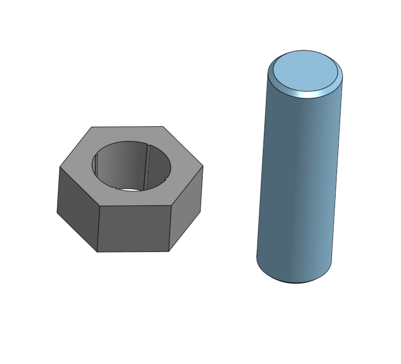
<p>Just learned about "crush ribs" from this video :</p> <p> <figure class="media"> <oembed url="https://youtu.be/0h6dCeATkrU"></oembed> </figure> </p> <p>It looks like the solution to a problem I have dealt with before, so I had to try it out. I have labeled this "Version 01" as I may be creating additional test models.</p> <p>Short version :</p> <p>A general solution to the problem of getting one printed part to fit firmly into another while allowing for small discrepancies in print accuracy.</p> <p>Longer version :</p> <p>This print illustrates the basic design feature of a cylindrical shape that needs to fit firmly into a round hole. The ideal design for this is a "press fit" - the cylinder is just slightly large than the hole so that it fits tightly into the hole and is held in by friction. The problem with this design is that getting the precise fit is usually a matter of trial and error. Further, what works for one make of filament and printer may not work with a different filament or printer.</p> <p>The proposed solution to this problem is to use "crush ribs" in a tapered hole. The hole is tapered by adding "draft" to the design (that is, the walls of the hole are slanted or "drafted" by a small amount). In the drafted hole, small raised "ribs" are added in a symmetrical pattern.</p> <p>In the referenced video, a draft of 2 degrees is suggested, and a rib height of 0.2mm. Of course this is going to be different depending on the such factors as the print resolution, the size of the parts, and so on.</p> <p>In this print, I have provided a cylinder piece and some "hole" pieces. My hole pieces used a 0.3mm rib height with a symmetrical pattern of four ribs; the cylinder diameter is 15mm. Hole pieces were created with the following drafts and results :</p> <ul> <li>2° draft = somewhat loose fit, very easy to remove</li> <li>1° draft = good firm fit, not too difficult to remove</li> <li>1/2° draft = tight fit, difficult to remove</li> </ul> <p>The prints provided here serve these purposes :</p> <ul> <li>introduce the concept of crush ribs</li> <li>show how crush ribs work in practice</li> <li>develop a conceptual model for testing the method</li> <li>develop 3D CAD methods</li> </ul> <p>The last one is only indirectly related to 3D printing, but is important for me at least if I am going to be able to apply this method more generally.</p> <p>OnShape 3D CAD files for this :</p> <p><a href="https://cad.onshape.com/documents/b4493acd7fc8145bc0e7f9e7/w/567793688a7f5ef5584f3b04/e/25e93a0018f17576c3d09a97">https://cad.onshape.com/documents/b4493acd7fc8145bc0e7f9e7/w/567793688a7f5ef5584f3b04/e/25e93a0018f17576c3d09a97</a></p> <h3>Print instructions</h3><p>Use the 3mf files provided; otherwise :</p> <ul> <li>10% rectilinear infill</li> </ul>
With this file you will be able to print Test Print - Crush Ribs - Version 01 with your 3D printer. Click on the button and save the file on your computer to work, edit or customize your design. You can also find more 3D designs for printers on Test Print - Crush Ribs - Version 01.
