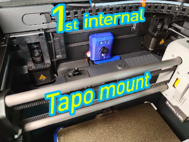
Tapo C110 V2.2 internal mount for P1S
prusaprinters
>> P1S print profileAfter getting annoyed to have the camera in the way of the front door, I designed this internal camera mount for the V2.2 of the Tapo C110 and the Bambu Lab P1S. Neither drilling holes into panels, nor disassembly is needed.The version of the camera is (what I assume) V2.2 according to the sticker on the back of the board (see 4th photo), and not V1 or V2 as categorized here in picture 4 (plastic of lens part is different). This is important because soldered components on the edges of the board might be different on other versions, where it slides into the case. You need to checked that in the marked areas in the photo so no tiny SMD components get damaged!________________________________________________________________________________________________________________Disclaimer: I can't be sure that this is not printed by people with two left feet as hands, so: Use at your own risk!Again this case is tested for Tapo C110 V2.2 . Using it for other versions without properly checking components might damage them when sliding into the case. Also, the current version, for now, requires soldering power cables to the back of the PCB and routing them outside the printer.Also, if you decide to print it in PLA (not recommended!) and the case makes a “camera sleepy” nod forward and the print head crashes into it, that's on you. (That free space there is tight!).________________________________________________________________________________________________________________Print in PETG or better. Not just the build chamber gets warm but the camera too. No greater layer height recommended so the notch of the lid part comes out right. 1. Clearance CheckFirst check if your version of the camera is clear in the marked spots. As mentioned above, there are at least three versions of this camera board and no tiny capacitors or other parts should be soldered in these spots on both sides, that could be damaged when sliding into the case. It has been tested on V2.2 according to the sticker on the back (see photo of step 5).If that's ok, print the parts. 2. Camera DisassemblyRemove the SD card and disassemble the camera by going in between the shiny black front and the white edges. Hooks are on each side exactly in the middle of each edge, not in the corners. Best to get something like phone repair spatulas in each and start prying carefully going from one to the next. Unplug speaker and that's it. Now TURN OFF the printer with the switch on the back and UNPLUG the Power cable to be save! 3. Wire RoutingYou can route the cables through the vent holes in the back of the printer. Shine a light through the holes, and look from the top, through the opening next to the left stepper motor to see where it needs to go. If bent the right way beforehand, they can be carefully pushed as far up to be in reach of pliers from the inside. If needed you can take the round original cable, going to the cable chain, out of the first holding clamp to have mor space. That way, taking off the backplate isn't necessary. Don't forget to put it back again. 4. (Optional) Focus adjustmentBefore you solder and put the camera into the case, you can adjust the fixed focus for the short distance. If you have a 0.2mm hotend, you can try to print El Jeffe's focus shims. With my 0,4mm hotend they came out too thick. I ended up using it as template (the file with the thick edges) to cut it out of glossy instruction manual paper which was 0.07mm. If you find a shop receipt with 0,05mm that would be even better. To put it in, disconnect the IR cable and take out the two lens screws on the back, lay it in between and assemble again. Make sure the paper or print doesn't leave a gap to keep dust out. 5. Wire solderingSolder power cables as marked on the photo, either directly to the camera PCB if you don't plan to remove it again, or like in my case, use e.g. a JST XH plug to make it removable. I glued the female plug to the side of the case as seen in the next picture. 6. Camera InstallationPut the camera into the case. The upper board with the infrared sensors might need a bit of a wiggle to slide in straight. Also there is a small rubber ring around the microphone on the bottom left of this board, be careful that it doesn't fall off while sliding in.After soldering everything and installing the camera, tape the wires between stepper motor and camera together. Add cable cover. 7. Final Checkupcorrectly screw the other end of the cables into the terminal of the female barrel jack you can find in the BOM. (outer side is ground, inside of barrel is plus).Double check all points for polarity, plug in camera and printer and enjoy!________________________________________________________________________________________________________________Bill of Materials:Female 5.5mm x 2.5mm DC Connector with screw terminals like these (just as an example, there may be cheaper ones sold per piece in your region).Wires: I used 0.5mm² / AWG24 wires. A little smaller crosssection may be feasible but I find 0.5mm² best to work with.optional: one male and one female JST XH 2-pin plug
With this file you will be able to print Tapo C110 V2.2 internal mount for P1S with your 3D printer. Click on the button and save the file on your computer to work, edit or customize your design. You can also find more 3D designs for printers on Tapo C110 V2.2 internal mount for P1S.
