Tactile Logic Gates
pinshape
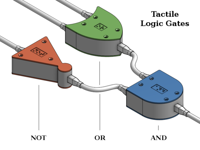
Tactile Logic Gates The five boxes presented here serve as a prototype and proof-of-concept for a set of educational toys specifically designed to teach simple propositional logic and logic circuitry to visually impaired individuals. These boxes feature physical representations of the three basic logic gates (AND, OR, NOT), shaped like their traditional representations in logic circuit diagrams. They perform their respective functions and can be connected using safe cables to create a working circuit. Inputs are represented by the Input Box, which has a simple on/off switch to toggle between TRUE or FALSE inputs. Outputs are represented by the Output Box, which lifts or lowers a tactile indicator based on the signal. The sockets have six pins, but only three cores - power, ground, and signal - are required for connection. The plugs can be inserted in either orientation, offering flexibility and convenience. Print Settings Layer Height: I printed all of these designs with PLA at 0.2mm layer height, ensuring sufficient tolerance for interlocking parts. Note that the braille text is 0.4mm thick. Dimensions for braille characters were taken from brailleauthority.org, recommending a thickness of 0.48mm. However, I opted to stay closer to standard layer heights. Extrusion Width: An extrusion width of 0.42mm worked well for me when printing thin walls using Simplify3D. Your mileage may vary. Support Structures: The only parts requiring support structures are the various Walls due to their sockets. Rest assured, the rest can be printed without them. Overhangs are limited to 45° for your convenience. To-Do A shopping list is needed for the components required to build electronic circuits. The prototype uses readily available components, which I will not inflict on the world just yet. A 3D design for a Fan-Out component is necessary to allow a single output to be duplicated into multiple leads. Smaller boxes are needed for all components; these current designs are big and awkward. A more efficient actuator should be used in the Output-Box. The current DC motor stalls against a barrier, pushing the indicator up. It requires springs to pull the indicator down again, which is inefficient. Acknowledgments Many thanks go out to Neil Thomas for helping me with electrical circuit designs. As a 3D printing enthusiast and software developer, I am a complete rookie when it comes to electronics, and found myself woefully underprepared. Without Neil's help, I could not have made this progress as quickly. Design Process I designed the 3D parts in OnShape. The original designs are public and can be accessed for modification. Feel free to play around with them! The attached photos showcase various stages of my design process. Videos of testing the output mechanism are also available.
With this file you will be able to print Tactile Logic Gates with your 3D printer. Click on the button and save the file on your computer to work, edit or customize your design. You can also find more 3D designs for printers on Tactile Logic Gates.