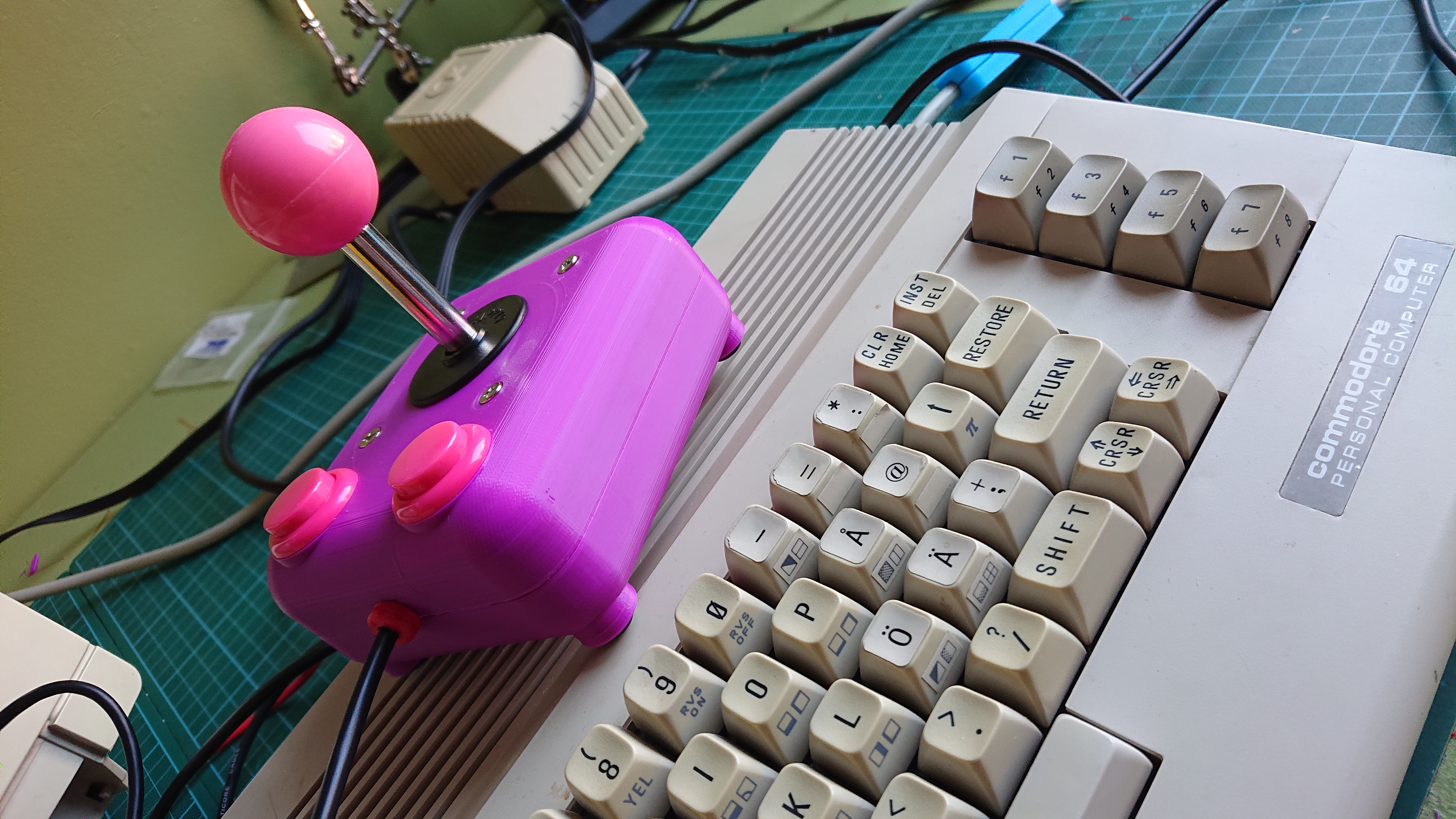
TacFree - An arcade style joystick for retro computers
prusaprinters
<p>This is a homage to my favorite stick from my misspent youth, the venerable Tac-2 by SunCom.<br>The guts are off the shelf arcade parts. The only part that can be tricky to source is a joystick extension cable for Commodore/Atari computers.</p><p><strong>Version 2</strong></p><p>Added a simplified bottom shell.</p><p><strong>Version 3</strong></p><p>Added a bottom shell with room for electronics and a trap door that can cover any buttons or switches you might like to add.</p><p> </p><h3>Print instructions</h3><p> </p><h3>BOM</h3><p> </p><ul><li>1 x Zippyy JS3-1 arcade joystick</li><li>1 x M6 thread ball for joystick</li><li>2 x SanStar PB8 24x30mm arcade button or similar</li><li>1 x Joystick extension cable for 9 pin DIN</li><li>4 x M3 nuts</li><li>4 x M3x25mm screws</li><li>4 x 6mm rubber feet (optional)</li><li>Perfboard</li><li>Multicolored cables</li></ul><p> </p><h3>Assembly</h3><p><br>I printed the shell in 3DPrima Easy Print PLA and the grommet in 3DPrima Select Flex.</p><p> </p><p> </p><h4>Preparing the shell</h4><p><br>Insert the M3 nuts in the pockets in the top of the shell. Two in the rear and two in the sockets inside the holes for the buttons.<br>If they are hard to locate, check the pocket for stray filament.<br>Test fit the grommet in the notch between the buttons, adjust as necessary.</p><p> </p><p> </p><h4>Preparing the cable</h4><p><br>Remove the male end (the one with visible pins inside a socket) from the cable, leave a few cm of the cable in case you want to reuse it later.</p><p> </p><p>Put the grommet on the cable, the rounded end should face the female connector.</p><p>Peal off roughly 4-5cm of the rubber coating. Remove any stray threads or shielding.</p><p>Tie a simple knot on the cable, just below where you pealed it. This is for strain relief on the soldered connections.<br>Peal the ends of the exposed leads. You may want to tin these, but I found them hard to shape so that they easily slide into the perfboard.</p><p>Cut out a roughly 25x20mm sized piece of perfboard. It should fit snugly into the socket between the buttons on the top half of the shell.</p><p>Now we have to map the color of the leads to a pin number so that we can connect them to the correct switch later.<br>I used a multimeter in continuity mode to check which pin mapped to which color, but you could use a battery, an LED and some wire f ex.</p><p>When you're done you should have a table like below. I found what each pin does in the C=64 users guide, some thing were better before!</p><figure class="table"><table><tbody><tr><th>Pin</th><th>Function</th><th>Color</th></tr><tr><th>1</th><th>Up</th><th>Red</th></tr><tr><th>2</th><th>Down</th><th>Black</th></tr><tr><th>3</th><th>Left</th><th>Gray</th></tr><tr><th>4</th><th>Right</th><th>Orange</th></tr><tr><th>5</th><th> </th><th>Brown</th></tr><tr><th>6</th><th>Button 1</th><th>Green</th></tr><tr><th>7</th><th> </th><th>White</th></tr><tr><th>8</th><th>Ground</th><th>Blue</th></tr><tr><th>9</th><th>Button 2</th><th>Yellow</th></tr></tbody></table></figure><p>Solder each lead to the perfboard, even the ones that doesn't do anything.</p><p> </p><h4>Preparing the stick</h4><p><br>Remove the metal mounting plate and plastic cover disc. Save the screws for later.</p><p> </p><p>Remove the green plastic plate on the bottom of the stick. It's used for restricting movement and we won't need it.<br>Look at your table and find which color is ground. Use a wire of the same color to connect one terminal on all of the four switches, I used the one that points straight out. Leave enough wire to connect to the perfboard later. Be generous, you can always shorten it later.</p><p>Pick one direction to be up, I used the side with the printed logo. For each switch, mark it with the direction it triggers. This is reversed though. So if you push the stick up, the switch facing you is triggered. Left is right and vice versa.<br>For each direction, look up its lead color in the table and connect a matching wire and make sure that it's at least as long as the ground wire.</p><p> </p><h4>Preparing the buttons</h4><p><br>Solder a ground wire and a wire with a color matching the buttons in the table. If you don't want/need two button support. Use the button one color.</p><p> </p><p> </p><h4>Final assembly</h4><p><br>Insert the stick and fasten with the screws you set aside. You may have to bend the terminals that stick out a bit. Make sure that up is facing up!</p><p> </p><p>Insert the buttons, keep track of which one is B1 and B2.</p><p>Insert the cable, seat the grommet. Solder up the connections from the switches to the matching colors on the perfboard. Make sure all the grounds are connected together. Test all the connections like you did when mapping the colors.</p><p>Now all you have to do is to screw on the bottom half using the M3 screws!</p><p>And yeah, add the rubber feet if you're into that thing ;)</p>
With this file you will be able to print TacFree - An arcade style joystick for retro computers with your 3D printer. Click on the button and save the file on your computer to work, edit or customize your design. You can also find more 3D designs for printers on TacFree - An arcade style joystick for retro computers.
