Switchboard for IKEA LACK
thingiverse
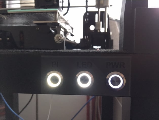
This is my sleek and user-friendly print switchboard designed for 19 mm LED switches that seamlessly fit into the IKEA LACK system. Instructions and Images are conveniently located in the Instructions section below. Enjoy! Print Settings: Printer: ANET A8 Rafts: Doesn't Matter Supports: No Resolution: 0.2 Infill: 20 % How I Designed This FreeCAD Instructions What you need: The switches in suitable voltages can be purchased here. You'll require 2 x 12 V for the Raspberry and LEDs, as well as 1 x 230 V (depending on your line voltage, mine is 230 V). Choose any color you prefer. A 12 V to 5 V Step-Down-Module is needed to power the Raspberry Pi via GPIO. The converter can be purchased here. Find instructions for powering your Raspberry using GPIO pins here. 1 x 20 mm drill for drilling holes into the table. Approximately 1.5 qmm wires for the 12 V switches, and 2.5 qmm wires for the power switch. And finally, the printed switchboard. Instructions: 1. Solder the switches as depicted in the wiring diagram (only found one in German). Be cautious of your current voltage and test it carefully before proceeding to step 2! 2. Drill three holes at the correct positions so that the board fits perfectly into them in the end. It's quite easy to drill through the table due to its low thickness. 3. Drill or cut (or both, like I did) a big hole with the length of the board to access your wires and switches mounted to the table by the nut (in the image, the wires were not soldered completely). 4. If you've tested every switch to ensure it's working properly, you can already feed them through the board and secure them by tightening the nuts from behind as seen in the picture above. I recommend labeling each wire with its functionality to avoid confusion with this mass of wires and the potentially hazardous voltage. 5. The switchboard doesn't need to be glued to the table; if you've attached the switches correctly, it should remain in place on its own. 6. Finally, connect all wires to their correct pins. The PSU should resemble this: Power input (L, N) of the PSU connected to the 7. Don't forget to convert the voltage coming out of the PI switch from 12 V to 5 V so you can power your Raspberry Pi. If you still have questions relating to the switches, feel free to leave a comment.
With this file you will be able to print Switchboard for IKEA LACK with your 3D printer. Click on the button and save the file on your computer to work, edit or customize your design. You can also find more 3D designs for printers on Switchboard for IKEA LACK.