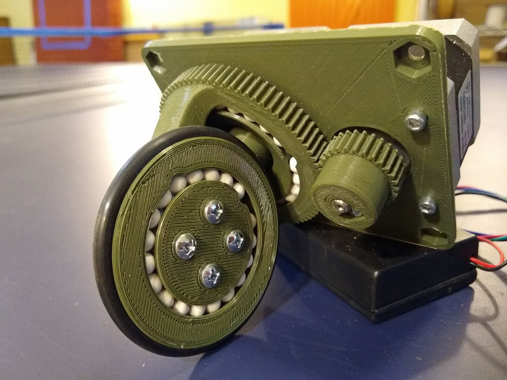
Swerve Drive for NEMA 17 Motors
thingiverse
This versatile swerve drive system is essentially a powered caster that enables the creation of omnidirectional robots. Unlike Mechanum wheels or omni wheels, it does not suffer from the issue of tiny roller diameters, making it ideal for navigating irregular surfaces. Designed specifically for NEMA 17 stepper motors, two swerve modules can be conveniently controlled by a single 3D printer controller board using G-codes. The design drives the wheel through a central motor shaft via a 4:1 bevel gear set. The wheel is then mounted on a rotating steering carriage that is driven by a second motor via a 28:80 spur gear set. The wheel and the steering carriage are supported by integral full-compliment bearings made using 6mm dia. airsoft BBs. 3/16" thick x 2.5" diameter o-rings are used for the tires. I have also included files for a passive caster for creating a minimal robot base. Note that at least two swerve drive modules are required to build a robot, but you can use 3, 4 (or even more) drive modules with the proper controller code. Watch it in action at: https://youtu.be/s3WDztd8JmQ (Note: This design is identical to a previous posting, which for some reason, Thingiverse failed to fully recognize.) **Required Parts** In addition to the 3D printed parts, you will need the following for each module: 1 - 3/16" thick x 2.5" O.D. o-ring 2 - NEMA 17 stepper motors 4 - M3 x 5mm panhead screws 2 - M3 x 8mm panhead screws 4 - 6-23 x 5mm screws 19 - 6mm dia. airsoft BBs 1 - OPB606A optical sensor (for homing the steering axis) **Assembly Instructions** To assemble the swerve drive module, follow these steps: 1. Assemble the wheel bearing to the wheel hub using 19 balls. 2. Screw the hub to the side of the steering carriage with the four 6-32 screws. 3. The bevel pinion gear should mesh with the wheel bevel gear without over-meshing and without any backlash. 4. If the gear fit is too tight or too loose, you will need to slide the pinion gear up or down on the motor shaft. 5. Insert the second motor into the remaining hole in the base. 6. Screw the motor in place with the two exposed holes using the longer M3 screws. 7. Add a 6-32 nut and set screw to the pinion28 hub, slide onto the motor shaft, and tighten in place. **Usage Notes** I suggest first assembling just two swerve drive modules and a castor into a bare frame to get you going with your controller code. I used an old 3D printer controller board (Printrboard) I had lying around, hooking up one module to the X and Y axes and the other to the Z and E axes. You can then just start sending G-code commands at the controller to make things move. Also note that the steering and drive axes are somewhat coupled. As you move the steering carriage, the wheel will also rotate. If you rotate the steering carriage by one full rotation, you'll see the wheel moves backwards by 1/4 rotation. Lastly, for homing the steering axis, I added a hole in the base for a downward-looking retroreflective optical sensor (OPB606A). There is a square gap in the top surface of the steering gear that aligns with the sensor so that it is triggered once per revolution.
With this file you will be able to print Swerve Drive for NEMA 17 Motors with your 3D printer. Click on the button and save the file on your computer to work, edit or customize your design. You can also find more 3D designs for printers on Swerve Drive for NEMA 17 Motors.
