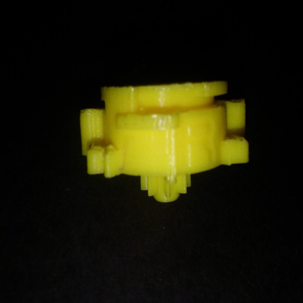
Spin Gear V3 (Beyblade Part)
thingiverse
I was inspired to create an improved version of Tightskin's spin gear design after receiving my first official plastic gen beyblade. I made many changes to this design so that parts can be properly mixed with those of official spin gears. The sides are now inscribed with either an L or R, depending on the spin direction it grants (left or right), making it easier to differentiate between them once printed. One change is that the hole at the bottom of the core has been widened slightly; the metal tip of Customize Change Base actually requires it, as one picture shows. A couple of photos show a comparison between the three different spin gear versions I've made. The yellow one is this version, the red and blue one is an official one, and the white one is Tightskin's version. When looking closer at the core file, I discovered that it was actually two different pieces all along. I've put separate and combined versions of this online. If you print the separated version, you can insert a metal cylinder, though you'll need glue to keep the two halves together. The Spin Gear is at the center of a beyblade, holding every other part together. This itself is made up of two parts: the core and shell. The core holds weights of different kinds, usually being regular metal or a magnet. The shell determines the direction that the bey will spin in, and allows the beyblade to connect to a launcher. The core fits into the shell by lining up a rectangular tab on the core with a similar rectangular slot on the inner part of a shell. A second shell is needed for full assembly. To attach it to the blade base, slide the bottom of the assembled spin gear onto the matching space in the blade base. When fully inserted, you should be able to press the pegs of the blade base all the way in to lock the spin gear in place. Two small tabs at the end of the pegs should hook onto the circular bottom lip of the core. Weight disks have two pairs of tabs on the inside, with each tab of each pair being separated by a small, rounded notch. This notch should line up with rounded tabs on the sides of the spin gear. The weight disk will be a loose fit and won't directly lock in place. Rather, once the attack ring is attached, the weight disk will be clamped between the spin gear and attack ring. The attack ring has two wide, thin, inner tabs on its bottom. The top of the spin gear is almost a perfect, flat circle except for two wide notches. Line these up to attach the attack ring, and twist it as far as it will go. If everything worked right, the inner tabs of the weight disk should be completely covered by the attack ring.
With this file you will be able to print Spin Gear V3 (Beyblade Part) with your 3D printer. Click on the button and save the file on your computer to work, edit or customize your design. You can also find more 3D designs for printers on Spin Gear V3 (Beyblade Part).
