Soap dish with hand wash timer
prusaprinters
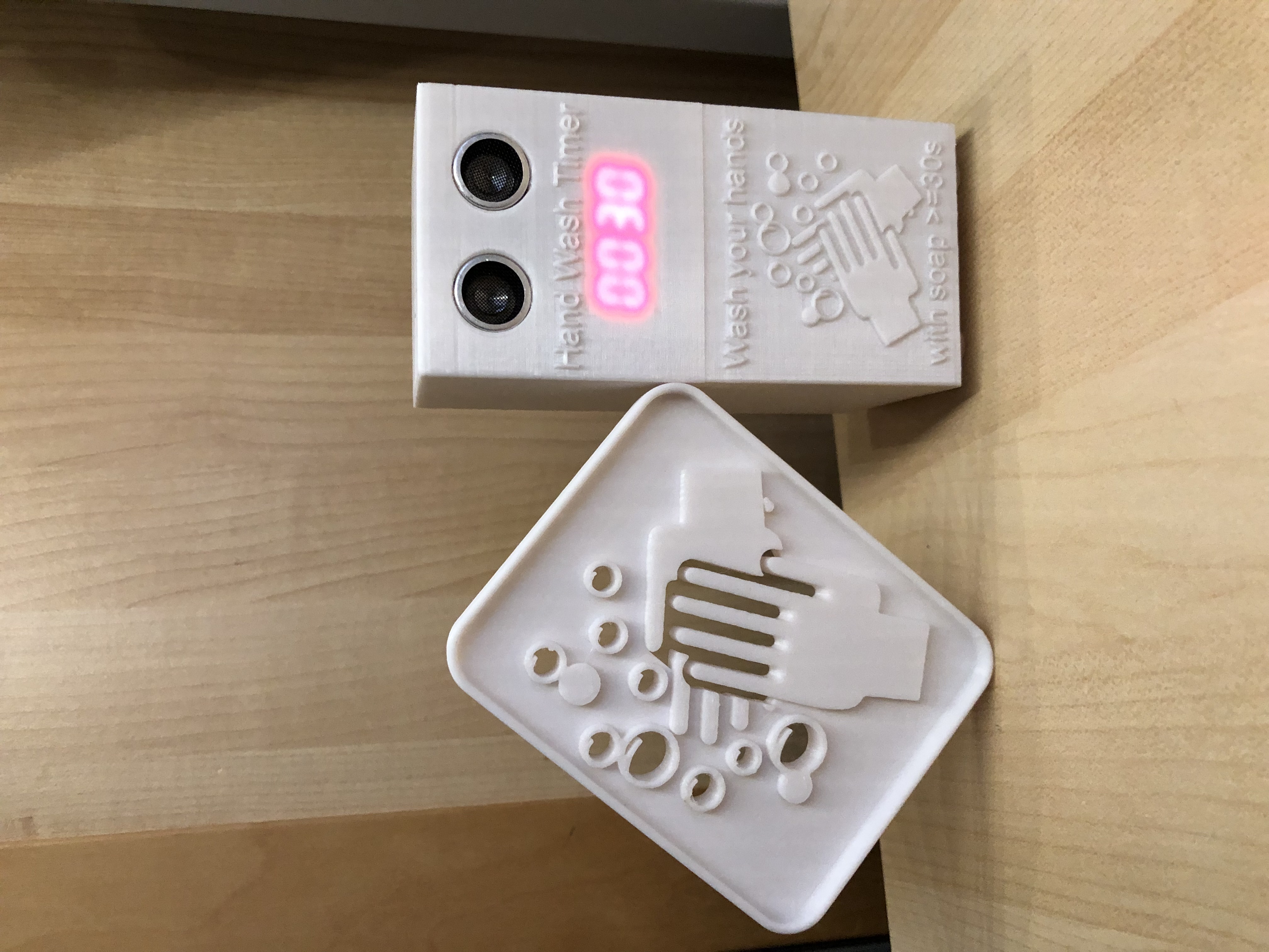
<p>Soap dish with a seperate hand wash timer using an ultrasonic sensor that activates a 7-segment display showing a 30 seconds countdown.</p><p><br><strong>Notes: </strong></p><ul><li>Updated the code on 14.08.2022. See changes and notes below.</li><li>Updated the code on 17.08.2022 to turn off the internal D1 mini LED during boot to reduce power usage.</li></ul><p> </p><p><strong>Features:</strong></p><ul><li>Soap dish with hand wash timer set to 30 seconds.</li><li>The soap dish is “floating” in the air to let the water run out. To the 4 small foots i added some rubber feet in the bottom to let it sit better on the sink.</li><li>The timer is activated by an ultrasonic sensor when you put your hand in front of the sensor in about 25cm distance for at least 5 seconds. This action activates a 7-segment display that shows a 30 seconds countdown. After the countdown the display turns off again to save power. The ESP8266 will deep sleep for 5 seconds to save battery power.</li><li>The circuit is powered by an 1100mAh LiPo battery that can be recharged with the used battery shield via Micro-USB.</li><li>For the ESP8266 Arduino code only 1 extra library is needed for the "<a href="https://github.com/avishorp/TM1637">TM1637</a>" display. This can be found in the Arduino IDE in the library manger too.</li><li>The display is placed behind the top case to reduce the possibility for water to get in the case and it looks better when it is not directly visible. The display looks odd on the pictures because the camera does not handle it right. It looks better in usage. </li><li>Code for Arduino IDE for an ESP8266 “D1 mini” can be found in my <a href="https://github.com/AWSW-de/Soap-dish-with-hand-wash-timer">GitHub repository</a>, so that you can change the values for the distance and the timer time in the top of the code. See info below:<br> </li></ul><p><strong>Changing the parameters in the code:</strong></p><pre><code class="language-plaintext">// Change program paramters here:// ##############################int defcount = 30; // Default timer countdown time = 30s int distance = 25; // Default distance to start the timerint debugmode = 0; // Use serial output in debug mode = 1 only to save power</code></pre><p>These 2 parameters might be all for you need to change in the top section of the code.</p><p>The desired distance can easily be estimated in the serial monitor of the Arduino IDE. The default is set to 25 which results in 25-27cm of distance to activate the timer depending on the tolerances of the HR-SR04 ultrasonic sensors. I used a 30cm ruler in front of the sensor and had a look in the serial monitor output to get the desired default value. When nothing is placed in front of the sensor it toggles around a value of 100-130 in distance. </p><p> </p><p><strong>Parts used:</strong></p><ul><li>Ultrasonic sensor “<a href="https://www.az-delivery.de/products/3er-set-hc-sr04-ultraschallmodule">HC-SR04</a>”</li><li>TM1637 7-segment display "<a href="https://www.az-delivery.de/products/4-digit-display">TM1637</a>": </li><li>ESP 8266 “<a href="https://www.az-delivery.de/products/d1-mini">D1 mini</a>”</li><li>D1 mini “<a href="https://www.az-delivery.de/products/batterie-shield-fuer-lithium-batterien-fuer-d1-mini">battery shield board</a>” with JST plug to recharge the LiPo battery</li><li>D1 mini “<a href="https://www.az-delivery.de/products/prototyping-shield-fur-d1-mini?variant=19881108504672">prototype shield</a>”</li><li><a href="https://www.amazon.de/dp/B08FD39Y5R">1100mAh LiPo battery with JST plug</a></li><li>2x M3x10 screws to hold the parts in the top part in place</li></ul><p><br><strong>Printing instructions:</strong></p><ul><li>All parts were printed with the 0.2 speed profile with some slight changes:<ul><li>The skirt line was disabled.</li><li>Except the holder and 4 foot parts all other ones were printed with a 5mm brim.</li><li>Supports are needed for the ”top“ part as shown in the pictures with a support cube. The dimensions of it are shown in the picture. </li><li>Supports are needed for the 4 foots from the bed.</li><li>The temperature was set to 215°C for the nozzle and 60°C for the bed.</li></ul></li><li>The strange lines in the “top“ and ‘bottom“ part showed up with the used white PLA for the first time in my last print of these parts. I have not checked again with my usual used PLA, but this looks a bit odd to me. So this should look usually better. If you have an idea to this, please let me know. =)</li></ul><p> </p><p><strong>Stacking the D1 mini boards and info about the to use connectors to make this work:</strong></p><ul><li>Please have a look at these these pictures and the used connectors.</li><li>The connectors usually come with these D1 mini boards and D1 mini shields and they are used to reduce the amount of needed wires significantly.</li><li>Please double check that all the same pins are placed above each other, f.e. “RST” and “TX” in the same corner on all layers of these boards/shields.</li><li>The in the following table named wire connections all are soldered to the "prototype shield" as shown in the pictures below.</li></ul><p><img src="https://media.printables.com/media/prints/212345/rich_content/4163d3f4-21e6-428e-b68f-6a19744b2ce1/img_1666.jpg#%7B%22uuid%22%3A%22b5a38c88-d77a-4e62-8f95-69e36a25e3cb%22%2C%22w%22%3A4032%2C%22h%22%3A3024%7D"></p><figure class="image"><img src="https://media.printables.com/media/prints/212345/rich_content/68d3dc4c-13f9-488a-be17-9a4da9dd6a3b/img_1649.jpg#%7B%22uuid%22%3A%223fc4d07b-2380-4dd3-aea9-30ec69cec0e2%22%2C%22w%22%3A4032%2C%22h%22%3A3024%7D"></figure><figure class="image"><img src="https://media.printables.com/media/prints/212345/rich_content/c40f0343-fc59-41f3-bccf-bf116acad9e5/img_1650.jpg#%7B%22uuid%22%3A%22972c4cff-3777-4fc9-9b6b-33518a37afcd%22%2C%22w%22%3A4032%2C%22h%22%3A3024%7D"></figure><p> </p><p><strong>Wiring the parts:</strong></p><figure class="table"><table style="border-color:#000000;border-style:solid;"><thead><tr><th><strong>D1 mini to part →</strong></th><th><strong>7-segment display TM1637</strong></th><th><strong>Ultrasonic sensor HC-SR04</strong></th><th>Used wire color </th></tr></thead><tbody><tr><th>5V</th><td>VCC</td><td>VCC</td><td>red</td></tr><tr><th>G</th><td>GND</td><td>GND</td><td>black</td></tr><tr><th>D3</th><td>CLK</td><td> </td><td>yellow</td></tr><tr><th>D2</th><td>DIO</td><td> </td><td>white</td></tr><tr><th>D6</th><td> </td><td>Trig</td><td>orange</td></tr><tr><th>D5</th><td> </td><td>Echo</td><td>green</td></tr><tr><th>RST to D0 ***</th><td> </td><td> </td><td>blue</td></tr></tbody></table></figure><p>*** The blue wire connects the 2 pins of the D1 mini itself and needs to be added for the deep sleep function used from version 1.1.0 of the code on. See notes below.</p><p> </p><p>Here are some pictures of the wiring:</p><figure class="image"><img src="https://media.printables.com/media/prints/212345/rich_content/2e1fd797-3c48-4e35-a785-0d0009ca3d50/img_1657.jpg#%7B%22uuid%22%3A%229cf100d3-f954-42f4-b3d2-aae03a14a123%22%2C%22w%22%3A3024%2C%22h%22%3A4032%7D"></figure><figure class="image"><img src="https://media.printables.com/media/prints/212345/rich_content/71f974e4-ca43-445c-b983-98f63cce5f42/img_1659.jpg#%7B%22uuid%22%3A%22a67147ea-cbc8-4e1f-9e6e-7300e481604b%22%2C%22w%22%3A3024%2C%22h%22%3A4032%7D"></figure><p> </p><figure class="image"><img src="https://media.printables.com/media/prints/212345/rich_content/a80da890-3564-4905-a8d4-763b8a5c3166/img_0446.jpg#%7B%22uuid%22%3A%22a9cad726-9e0f-4624-baff-8324a2931aa7%22%2C%22w%22%3A4032%2C%22h%22%3A3024%7D"></figure><p>The 2 red and black wires are soldered together under the cicuit just with some more solder to make them join. All other wires next to the pin names get direct contact in the first row of holes next to the pin names.</p><p> </p><p>Ready for the first test, when you already uploaded the code to the D1 mini. :)</p><figure class="image"><img src="https://media.printables.com/media/prints/212345/rich_content/e562c1af-b5b0-4b65-84bf-49eb2e183427/img_1663.jpg#%7B%22uuid%22%3A%22e4ced611-c1a1-4c77-84ee-5e3632f52cc6%22%2C%22w%22%3A3024%2C%22h%22%3A4032%7D"></figure><p> </p><p>After the wiring the parts can be placed in the “top” part. See picture for more info.</p><p>The 2 small holder parts will keep the D1 mini and the LiPo battery in place.</p><figure class="image"><img src="https://media.printables.com/media/prints/212345/rich_content/4757c6a0-bf2a-45f5-982d-58190babc4e9/0e8c5882-3111-4191-8da3-ec5a794e51a7.jpeg#%7B%22uuid%22%3A%22f3ce5ab2-484f-4c0e-b475-a25b301652a4%22%2C%22w%22%3A3024%2C%22h%22%3A4032%7D"></figure><p>All wires used were at about 8cm in length. That was a bit tight. If i would make this project again i would go for 13-15cm just to make the assembly more easy and to be able to put them arround the LiPo holder.</p><p> </p><p><strong>Final words:</strong></p><p>Originally i just wanted to create a small soap dish that i would like and then i thought about the timer code i had lying around on my code server and now it finally got placed into a case and comes to usage after 2 years…</p><p>Please let me know what you think, because that turned out in a bit more work on this project and i hope you like it. =)</p><p> </p><p> </p><p><strong>Last important notes:</strong></p><ul><li>⚠ Of course some security note is required for this project that may be used in your bathroom. As you all know water and electronics are not good friends and can cause serious problems. Therefore it should be crystal clear that you will use this at your own risk and have to care about not getting the electronics wet or even under water. The case is made as tight and closed as possible, but it is no way near to be called waterproof! I placed the timer at a higher level on a shelf, so that is almost impossible that the device will get spilled with water. If you can read this you should be old enough to know that this is important to take care with such devices and you are responsible for this yourself.</li><li>⚠ For the note above and for usage as well as recharging actions it is also important to use a LiPo battery that contains a security circuit to prevent electronic shorts and over charging as well as under discharging, like the above linked one has. Saving here some cents can cause some serious problems too, so better be safe than sorry here as well.</li><li>Used <a href="https://www.iconspng.com/download/22541">picture</a> license info - as quote:<br>“Licencing! Wash Your Hands Sign SVG vector - The pictures are free for personal and even for commercial use. You can modify, copy and distribute the photos on iconspng.com. All without asking for permission or setting a link to the source. So, attribution is not required.”</li></ul><p> </p><p><br><strong>Edit on 14.08.2022:</strong> Added new code version with deep sleep function so that the ESP will reduce its power usage for 5 seconds between the measurements dramatically. You will need to add an additional wire from RST to D0 for this function. Otherwise the ESP will never wake up again. See changes above. This should ensure that the battery will last much longer… To transfer the code to the D1 mini board you may need to separeate the D1 mini from the board with the wires to be able to start the transmission. This is an old disadvantage of these ESP8266 boards when used with deep sleep timers…</p><p> </p><p>Happy printing :)</p>
With this file you will be able to print Soap dish with hand wash timer with your 3D printer. Click on the button and save the file on your computer to work, edit or customize your design. You can also find more 3D designs for printers on Soap dish with hand wash timer.