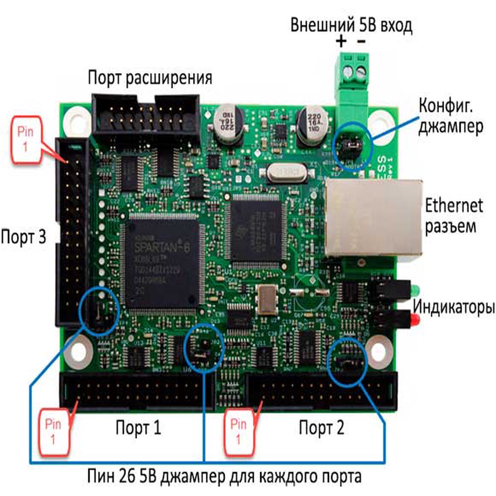
Smoothstepper to stepper motor driver pairing
thingiverse
A Stepper Motor Driver Connection Circuit Diagram is Needed, Including a Fritzing Scheme and MACH4 Ping Assignment for Two Y-Axis Motors. To create an effective Stepper Motor Driver Connection Circuit Diagram, one must first understand the basics of stepper motor technology. A stepper motor is a type of brushless DC electric motor that divides a full rotation into equal steps. It has a number of discrete torque outputs at each position and provides accurate positioning control. The connection circuit diagram should include a Fritzing scheme for visual representation and organization, which will make it easier to understand the relationship between components. A Fritzing scheme is an open-source tool that allows users to create and share electronic designs. It uses a drag-and-drop interface to design circuits, making it easy to visualize and modify connections. MACH4 ping assignment for two Y-axis motors is also required in this circuit diagram. MACH4 is a G-code interpreter for CNC machines, including 3D printers and milling machines. The ping assignment allows users to assign specific ping commands to each motor, enabling precise control over the movement of the stepper motors. Here's a possible connection circuit diagram that includes a Fritzing scheme and MACH4 ping assignment: 1. Stepper Motor Drivers: Two stepper motor drivers are needed for two Y-axis motors. These drivers provide the necessary current and voltage to drive the stepper motors. 2. Power Supply: A power supply is required to power the stepper motor drivers. The power supply should be able to provide sufficient current and voltage to drive both stepper motors. 3. Fritzing Scheme: A Fritzing scheme can be created to visualize the connection circuit diagram. This will make it easier to understand the relationship between components and identify any potential issues. 4. MACH4 Ping Assignment: The MACH4 ping assignment is required to assign specific ping commands to each motor. This allows users to precisely control the movement of the stepper motors. In conclusion, a Stepper Motor Driver Connection Circuit Diagram that includes a Fritzing scheme and MACH4 ping assignment for two Y-axis motors is necessary for effective stepper motor operation. By following these steps, users can create an accurate connection circuit diagram that enables precise control over the movement of the stepper motors.
With this file you will be able to print Smoothstepper to stepper motor driver pairing with your 3D printer. Click on the button and save the file on your computer to work, edit or customize your design. You can also find more 3D designs for printers on Smoothstepper to stepper motor driver pairing.
