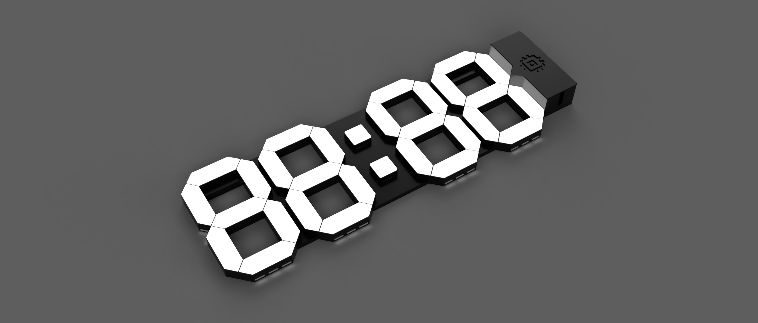
Smart Home 7-Segment Wall Clock
prusaprinters
<h3>7 Segment Wall Clock</h3><p>Main part of the clock is a WS2812B 5V LED strip. I took the one with 100 LEDs per 1m. Thus, 3 LEDs would fit in one segment. The colon is a pretty tight fit already, so it might be difficult for all bigger LED strip segments. </p><p>You'll need some plastic glue, cables, the LEDs of course, basic electronics components (details in the electronics section) and of course a steady hand for the soldering. :)</p><p> </p><h4>Clock Case</h4><p>Please print the case with 2 different colors. I recommend the boxes to be black and the plates on top to be white or semi transparent so that the LED light shines through nice and evenly. A semi-transparent filament might help here, if it is too thick. </p><p>Mine is printed with 0.2mm layer thickness with white EXTRUDR filament and the light inside is nicely visible. </p><p> </p><h4>Electric Circuit</h4><p><strong>ATTENTION: </strong>ALL ELECTRICAL WIRING IS PERFORMED AT YOUR OWN RISK. THERE IS NO WARRENTY FOR YOUR OWN SAFETY NOR THE COMPLETENESS OR CORRECTNESS OF THE SHOWN CIRCUITRY. </p><p>And… Do not work with mains power if you don't have the necessary skills.</p><p>The overall wiring is pretty straight forward: </p><figure class="image"><img src="https://media.prusaprinters.org/media/prints/77362/rich_content/ca07f24a-113b-4931-b93d-161f3cbbda52/image.png#%7B%22uuid%22%3A%22da1099d4-a3d0-4ed0-ba3c-650f2047d4a6%22%2C%22w%22%3A1326%2C%22h%22%3A1221%7D"></figure><p> </p><p>My finished circuit board looked something like this: </p><figure class="image"><img src="https://media.prusaprinters.org/media/prints/77362/rich_content/aa5c886f-18ed-44e6-b77d-244e4921435f/image.png#%7B%22uuid%22%3A%22f650f2d0-bd49-4591-a545-fc8620acd1c0%22%2C%22w%22%3A2071%2C%22h%22%3A1065%7D"></figure><p>Bottom right 5-pin connector is where my USB power supply is plugged in. Top right connector is for the ESP. But no I cannot guarantee that this will work for you as well, as it highly depends on your components and the capacitor sizes. </p><p>The thicc casing for the electronics is only required as my components were a little … not so space efficient. So, if you get yourself a tidier professionally manufactured PCB, you could get it a little neater. </p><p><strong>Electrical Components needed:</strong></p><ul><li>The LED strip of course (WS2812B, 100LEDs per meter)</li><li>An ESP8266-01 module</li><li>A micro USB port or any other 5V power connector</li><li>Some voltage converter. I used an LD33VC / LD117AV33. Please check the according capacitor setup.</li><li>Additionally, get yourself a couple of current limiting resistors. I used 1K for the chip enable pin and 220 for the data pin of the LED strip.</li></ul><p><i>Note:</i> The bottom part of the schematic above shows the typical LED strip contents. You don't need to worry about it too much, but I placed it here for the sake of completeness and understanding.</p><figure class="image image-style-align-left image_resized" style="width:18.81%;"><img src="https://media.prusaprinters.org/media/prints/77362/rich_content/02cafe5d-1f7b-4271-a1e2-6263e6debfaa/1280px-7segment_24svg.png#%7B%22uuid%22%3A%22d12007fa-748a-4538-9e4e-c04060da5628%22%2C%22w%22%3A1280%2C%22h%22%3A2060%7D"></figure><p>For the code example to work, it is required that you wire the LED strip parts as blocks of 3 LEDs. <br>Wiring of each segment is <code>C → D → E → G → B → A → F</code>. </p><p>Yeah - I know. The soldering is some work and it takes a moment. But after the first segment, it went quite smoothly.</p><p>In the middle of the four segments, the colon has to be wired in as one LED each. Just put on cables before inserting it into the little brick. Then glue it into the bigger connector piece. </p><p>If you want other wiring, please update the following number definitions inside this code block of the provided example.</p><pre><code class="language-cpp">bool ZERO[SEGMENT_CNT] = {1, 1, 1, 0, 1, 1, 1}; bool ONE[SEGMENT_CNT] = {1, 0, 0, 0, 1, 0, 0}; bool TWO[SEGMENT_CNT] = {0, 1, 1, 1, 1, 1, 0}; bool THREE[SEGMENT_CNT] = {1, 1, 0, 1, 1, 1, 0}; bool FOUR[SEGMENT_CNT] = {1, 0, 0, 1, 1, 0, 1}; bool FIVE[SEGMENT_CNT] = {1, 1, 0, 1, 0, 1, 1}; bool SIX[SEGMENT_CNT] = {1, 1, 1, 1, 0, 1, 1}; bool SEVEN[SEGMENT_CNT] = {1, 0, 0, 0, 1, 1, 0}; bool EIGHT[SEGMENT_CNT] = {1, 1, 1, 1, 1, 1, 1}; bool NINE[SEGMENT_CNT] = {1, 1, 0, 1, 1, 1, 1}; bool BLANK[SEGMENT_CNT] = {0, 0, 0, 0, 0, 0, 0}; bool UNDERSCORE[SEGMENT_CNT] = {0, 1, 0, 0, 0, 0, 0}; bool OVERSCORE[SEGMENT_CNT] = {0, 0, 0, 0, 0, 1, 0}; bool *ALL[] = {ZERO, ONE, TWO, THREE, FOUR, FIVE, SIX, SEVEN, EIGHT, NINE};</code></pre><p> </p><h4>Software</h4><p>The example requires you to replace the ssid and password with your data first. Secondly, replace your timezones with the according timezones. </p><p>Also, libraries are required to be installed: </p><ul><li>ESP-Libraries (Adafruit_ESP8266)</li><li>Adafruit_GFX_Library</li><li>ESPAsyncWebServer</li><li>Timezone</li><li>Adafruit_NeoPixel</li><li>NTPClient</li><li><i>(I hope to have all of them covered!)</i></li></ul><p>You need to get yourself one of these USB dongles or something comparable in order to flash the ESP. Don't forget to put the ESP into flashing mode. I will not go into details on how to flash an ESP8266-01 in this part.</p><p>The provided software example listens to the port 80. With <strong>GET :80/rgb</strong> you read the current RGB value and with the <strong>GET :80/rgb?color=caffee</strong> you set the current RGB value. </p><p>For a nice and seamless homekit integration I used the homebridge-http-rgb-bulb. Check out the project on GitHub: <a href="https://github.com/metbosch/homebridge-http-rgb-bulb">metbosch/homebridge-http-rgb-bulb</a></p><p> </p>
With this file you will be able to print Smart Home 7-Segment Wall Clock with your 3D printer. Click on the button and save the file on your computer to work, edit or customize your design. You can also find more 3D designs for printers on Smart Home 7-Segment Wall Clock.
