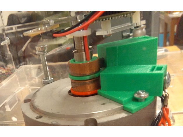
Slip Ring System
thingiverse
Slip rings for a project are excessively costly to purchase. Most lower-cost versions are incapable of carrying current for POV LED systems. This slip ring design was specifically created for a 3D POV system for a student. The brushes were salvaged from an old DC motor. The ring components themselves are a universal design that can be easily modified by adjusting the inside diameter to fit the motor shaft. This design accommodates a .5" motor shaft. Additionally, this slip ring setup has performed admirably. Power delivery is consistent when handling currents of 3+ Amps. Since parts were sourced from whatever was readily available, consider this design as an example. The concept is solid and it works well. Printer Settings Printer: Raise3D N2 Rafts: Yes Supports: No Resolution: .15 Infill: 50% Notes: The brush holder may require support depending on the specific design. In my case, it did. Usage The actual slip rings are made from .75" I.D. copper pipe. Solder the wire to the inside of the ring and position it in the slot that is insulated from the shaft. Use the slots closest to the shaft to carry the wires through. In theory, up to 5 slip rings can be used with this design. The rings are secured to the shaft using 4-40 set screws. Ensure the screws are short enough not to short out the copper ring to the shaft. The brush holder is a variable component. It largely depends on the type of carbon brushes used and how they will be mounted. Using the original design file (rsdoc), you can see how I created the holder and captured the brushes. The hardware used includes a #10 washer to capture the brush in the channel, a 10-32 nut, and a 10-32 bolt to connect and tighten the brush to the ring.
With this file you will be able to print Slip Ring System with your 3D printer. Click on the button and save the file on your computer to work, edit or customize your design. You can also find more 3D designs for printers on Slip Ring System.
