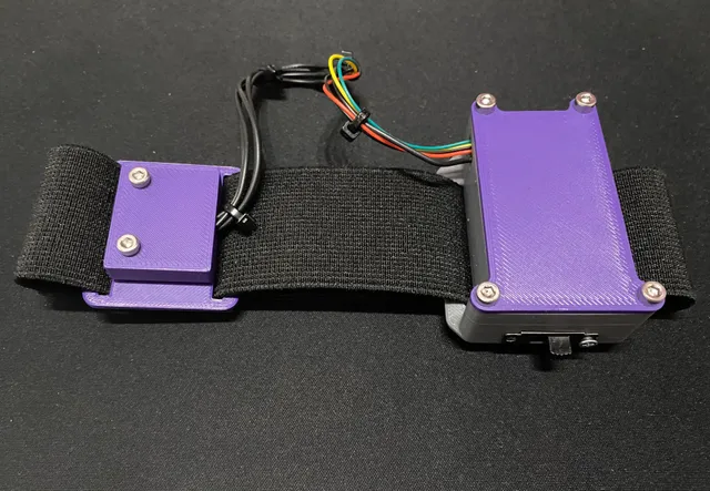
Slime VR Case with external sensor module
prusaprinters
Main ideaThis is the SlimeVR case for the DIY solutionThe main idea is to make IMU stick to a body as much as possible (this is especially actual for the thin parts of the body like ankles) and minimize shaking by reducing the mass of its caseAnother idea is to use the advantage of the new version of Wemos D1 Mini v4, which has the LOLIN I2C Port that uses standard JST-SH connector with GND, 3v3, SDA, and SCL pins - everything you need to connect IMUs like BMI160Components and SchematicsBased on the schematics and components listed in the SlimeVR docs with few specifics:- the Wemos D1 Mini board version must be 4 . The case is designed for the board with a flat bottom and a Type-C USB Port. Also, it has a JST-SH socket that simplifies the connecting of the external IMU sensor(s)- the battery dimensions must be equal to or less than 43x30x10 mm. The battery with this volume has ~1200mAh capacity- to use Wemos D1 mini JST-SH socket, you also need the Micro JST-SH 1.0mm 4-pin male connector plug- you need 4 M3x10 or longer screws for the main case (up to 20mm long), 2 M3x10 screws for the IMU sensor module, and at least 1 M2.5 screw (up to 10mm length) to mount the power switcher- the case is designed for the 40mm wide strapsThe approximate wires length is represented on the scheme below ( the scheme is copied from the https://docs.slimevr.dev/diy/tracker-schematics.html )Wires length for connecting tracker componentsAssembly manualThis part is work-in-progress. The general steps:- solder the wires to the power switcher and the battery (if it doesn't have any connectors)- insert the power switcher into the case. You may need to remove the protruding parts of the switcher sheet to align it with its metal part- solder the diodes to the charging board- solder the GND wire and resistor to the Wemos board (+D5 pin wire if you use BNO08X sensor)- solder the GND wire from the power switcher and the negative wire from the battery to the charger board- connect the positive battery wire and the resistor from the Wemos board to the charging board- connect the GND wire from the power switcher and diodes wire to the Wemos board- Make sure that there are no contacts that stick out from the boards too much! They can damage the battery that will be placed below them- place the charging board and Wemos board on the tray, insert the tray into the case. The charging board has a Type-C USB connector that is placed a little bit forward on its PCB, this side should be inserted at first- plug in the JST connector and guide it through the corresponding hole in the case (and the wire connected to the D5 pin if you use BNO08X sensor). Solder these wires to the IMU sensor- make sure that everything works. Switch on the device, upload the tracker firmware, check the serial output logs to make sure that the sensor works properly- insert and tighten the M2.5 screw to mount the power switcher- insert and tighten the M3 screws on the sensor case- position the lid on the main case - make sure that there are no wires in the places that correspond to the prominent parts on the lid. Insert and tighten the M3 screws on the main case. Be careful, do not over-tighten them ConclusionThis solution is already works, but still needs some polishingThe next improvements will be:- reliable fixation of the sensor cable. Right now it relies on the JST-SH connector toughness which is not intended to be used in the actively moved devices- making power switcher insertion process more convenient. Right now it requires some extra processing and using force- improving the assembly manual- better internal wires management. Right now the process of the inserting the tray and the lid may be messy in case when power switcher and battery wires are too long- flexible customisation. Right now the space for a battery is limited. It should be possible to customise the model by changing a global variables that represent the battery dimension and straps width- holes for the LED indicators- reducing the number of screws- creating the cases for wider range of IMUsPlease let me know if you have any other ideas or got the issue with current solution. Any feedback is appreciated
With this file you will be able to print Slime VR Case with external sensor module with your 3D printer. Click on the button and save the file on your computer to work, edit or customize your design. You can also find more 3D designs for printers on Slime VR Case with external sensor module.
