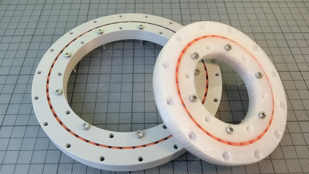
Slew Bearing, parametric Design with Fusion 360
thingiverse
3D printing enthusiasts swear by ball-bearings, but they frequently fail in real-world applications. Using Fusion 360, I designed a parametric model of a "Crossed Roller Slew Bearing" that delivers impressive accuracy and durability. The bearing's components, including the rollers, are 3D printed in separate parts and held together with screws that clamp the two inner race halves. Designing this slew bearing is a straightforward process, so I created a video tutorial to guide users through it in Fusion 360. With practice, a bearing can be designed from scratch in under 20 minutes. Students interested in 3D design should install Fusion 360 and walk through the tutorial to get hands-on experience. Watch my video tutorial on YouTube at https://youtu.be/5o4Fj8OxkB8 for a step-by-step guide. The downloadable 3D files include a large version with 48 rolls and a small version with only 10 rolls. Since the top and bottom halves of the race are symmetrical, both are available as STL files. If you need a bearing with custom dimensions, download the Fusion 360 CAD files from http://a360.co/2r9MFf5 or http://a360.co/2r9JnZf. I've provided two designs: a basic version with cylindrical rollers and a more advanced version with conic rollers.
With this file you will be able to print Slew Bearing, parametric Design with Fusion 360 with your 3D printer. Click on the button and save the file on your computer to work, edit or customize your design. You can also find more 3D designs for printers on Slew Bearing, parametric Design with Fusion 360.
