Slew Bearing, parametric Design with Fusion 360
pinshape
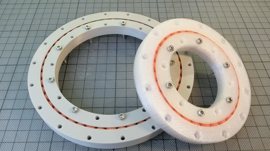
Summary: Ball-bearings are highly sought after for 3D printing, yet they frequently fail in real-world applications. Utilizing Fusion 360, I've created a parametric design for a "Crossed Roller Slew Bearing." The outcome is a remarkably accurate and robust bearing, comprising the rollers as separate parts to be 3D-printed. To secure the two halves of the inner race together, a few screws are necessary. The design process is surprisingly straightforward; thus, I've developed a video tutorial explaining how to design this slew bearing in Fusion 360. With some practice, such a bearing can be designed from scratch within 20 minutes or less. For students interested in 3D design, I recommend installing Fusion 360 and following the tutorial. The available 3D files for download include a large version with 48 rolls and a small version with only 10 rolls (top and bottom halves of the race are symmetrical but are provided as STLs for completeness). If needed, bearings with other dimensions can be designed using the CAD-files from Fusion 360. Two designs are available: a basic version featuring cylindrical rollers and a more advanced version showcasing conic rollers. Print Settings: Printer Brand: Ultimaker Printer: Ultimaker 2 Rafts: No Supports: No Resolution: 0.15 Infill: 35% Standards: NGSS Overview and Background: Lesson Plan and Activity: 1. Install Fusion 360. 2. Repeat the steps demonstrated in the video tutorial. 3. Print and test your own design. Materials Needed: A 3D printer. Some bolts and nuts. Duration of Lesson: 1-2 hours, plus time for 3D printing.
With this file you will be able to print Slew Bearing, parametric Design with Fusion 360 with your 3D printer. Click on the button and save the file on your computer to work, edit or customize your design. You can also find more 3D designs for printers on Slew Bearing, parametric Design with Fusion 360.
