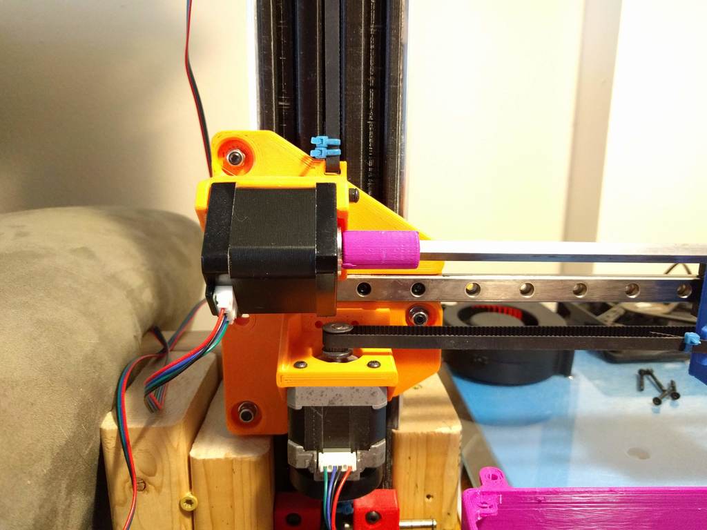
SLASH (Sliding LAteral SHaft) Extruder. Rigid shaft, remote mount, direct drive extruder, for Cartesian i3 printers
thingiverse
5/16/2020 Update: Added Model of Z Carriage and Pulley Mount for Opposite End of X Axis. ~~~~~~~~~~~~~~~~~~~~~~~~~~~~~~~~~~~~~~~~~ 5/5/2020 Update: Video of Extruder in Motion Here - Http://Imgur.Com/A/KaxNhek Progress on Building Printer Has Stalled for Now. ~~~~~~~~~~~~~~~~~~~~~~~~~~~~~~~~~~~~~~~~ This is a Development Level Design of a Shaft Driven Remote Drive Extruder. Unlike Flex Drive Extruders that Use a Springy Flex Shaft and Worm Gear, This Extruder Uses a Rigid 1/4" Steel Shaft, and a Sliding Herringbone Gear, Transmitting Torque to a Modified Titan Extruder. This design is made to suit a MGN12 Linear Rail, Titan Extruder Hardware, 1/4" Drive Shaft, and 33mm Center-to-Center Distance for the Herringbone Gears. The extruder itself is 75% Titan Extruder, modified to include the larger herringbone gear. The extruder motor mount is currently not integrated to the Z carriage, but it can be adapted or glued on. Some experimentation or mocking up may be required to position the motor correctly to allow the free rotation sliding of the X carriage. The shaft is 1/4" steel square rod from the home improvement store. Find the straightest piece you can. Brass, if you can get it, may be preferable. Key stock steel would be even better. Smaller sizes may work, but I fear too much smaller may not have enough interface with the gear to transmit torque. The gear ratio between the big and small herringbone gears is 3:1, same as the original Titan. So, use the same extruder steps/per MM as the Titan. Tips: - You may have to tweak the position of the filament guide in the extruder to get it to line up with the hobbed gear. - Use the larger herringbone gear as a guide to drill through the stock delrin Titan gear. - Use a bigger bit to drill a small countersink into the delrin gear. If possible, secure the two gears together with flat head M3 that will sit in the countersink. This prevents the screw heads from hitting the filament guide as the gear rotates. - The square steel shaft needs have the corners filed down slightly to fit into the 608zz bearing in the end support - The holes in plastic parts for M3 screws are sized to allow the screws to self tap into them. You could certainly modify them to use nuts. - Don't be afraid to file some things down. It may be needed to get some things to fit without rubbing Hardware Used: - MGN12 Linear Rail and H size carriage (20 mm square bolt pattern) - 1/4" steel square rod - (2) 608zz bearings - M3 screws, less than 20, various sizes - M5 screw and nut, to mount the idler lever - Titan extruder parts (for the case, is started with this one: Https://Www.Thingiverse.Com/Thing:1727220) Again, this is a Beta level of completion, at best, but it's workable and I release it to you all to develop further and adapt to your machines. Step files for everything except the gears is included. Those were from the parametric herringbone creator (see the Remix link), and then modified in MS 3d builder to add the holes modify the thickness and whatnot. Finally, I challenge you: Using this concept, implement a second drive shaft combined with some bevel gears, to relocate the Extruder motor to the bottom of the Z axis, off of the rising Z carriage.
With this file you will be able to print SLASH (Sliding LAteral SHaft) Extruder. Rigid shaft, remote mount, direct drive extruder, for Cartesian i3 printers with your 3D printer. Click on the button and save the file on your computer to work, edit or customize your design. You can also find more 3D designs for printers on SLASH (Sliding LAteral SHaft) Extruder. Rigid shaft, remote mount, direct drive extruder, for Cartesian i3 printers.
