Sketching Sine
thingiverse
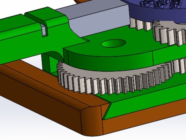
The Sine Mechanism is designed to help students grasp how the unitary circle works by allowing them easily appreciate the variables (frequency, amplitude, and phase angle) that make up a sine waveform and manipulate them to create diverse outputs. Based on the cam mechanism, this model also serves as an excellent example for engineers to understand its dynamics. A basic set of gears is provided, but the model can be customized by changing the ratio of the train gear, resulting in a change to the frequency of the Sine. How I Designed This Step 1: "Imagine Mathematics" I started by imagining how to translate math and its variables into a physical model. I realized that two-directional movement was necessary to create a sine waveform, with these movements connected because one depends on the other. Step 2: "First Movement" The rack is easy to understand, and 3D printers can create it. We solved the translation problem in one direction by using a pinion and rack. Step 3: "Output (Second Movement)" Since the pinion is connected to the input gear on the central floor (pinion is on the first floor), modifying the ratio of gears changes the frequency of the Sine, and the output gear connected to the gear on the third floor translates motion to the Cam wheel. This is how we solved the second-direction movement problem. The Cam moves back and forth, holding a pen in place. Sketchin' Sine Animation Project Objectives Objective A: Exemplify a basic mathematical function and its parameters through a tangible model, showing how each parameter affects the function based on their value. Objective B: Exemplify a cam mechanism and one of its multiple applications by analyzing from the beginning how gears and cams work together to produce a desirable output. Audiences Audience A: We focused on secondary school students, as they are first introduced to trigonometry. Learning is easiest when you can see, touch, and listen. Audience B: We focused on High School and engineering students, who find it difficult to imagine how each component moves in a way that affects another. In engineering, this type of mechanism can be confusing. Conceiving the Idea We started by imagining what would be helpful for students to understand trigonometry functions like Sine and Cosine. We sketched ideas on paper, "debugged" them, and used helpful websites like RushGear to find commercial gears and useful calculations. After that, we designed the model in Solidworks, a software easy to use with an awesome motion analysis feature. Results According to the simulation, everything seems to work fine. I don't have a 3D printer, but I can edit the model if anyone spots any errors. I tried designing the pieces so they could be printed well.
With this file you will be able to print Sketching Sine with your 3D printer. Click on the button and save the file on your computer to work, edit or customize your design. You can also find more 3D designs for printers on Sketching Sine.
