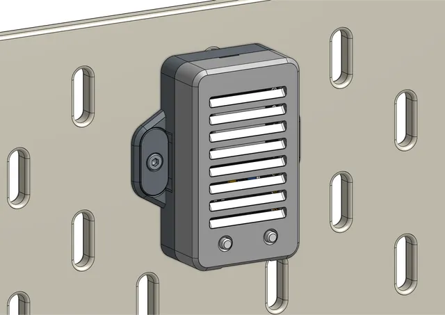
Skadis NodeMCU ESP-32S Case
prusaprinters
This is a case for the NodeMCU ESP-32S development board by Ai-Thinker that can be mounted on an Ikea Skadis pegboard. It uses Skadis T-Nuts for secure and easy installation.Note: This was made for the Micro USB version of the board and might not fit the USB-C version. Check out @GreatOldOne's remix if you use the USB-C version and this case doesn't work.This is a remix of the ESP8266 case by Crashoverride.Fits NodeMCU ESP-32S (MicroUSB version)Angled ventilation openings for dust protectionIdeal for Home Assistant Bluetooth Proxy / ESPHomeSTEP files available for easy remixingRead more about the Skadis T-Nuts Mounting System and check out the Skadis T-Nuts Collection for more Skadis accessories that use T-Nuts. BOMQtyDescriptionSourcing2M2.5 DIN934 Hex NutAliexpress2M2.5x12 (or longer) Socket Head Cap ScrewAliexpress Printed PartsQtyPart1NodeMCU ESP-32S Case Bottom.stl1NodeMCU ESP-32S Case Top USB Down.stl or NodeMCU ESP-32S Case Top USB Up.stl1**NodeMCU ESP-32S Case Buttons.stl2NodeMCU ESP-32S Alignment Guide.stl2Skadis T-Nut M2.5.stl** Optional partCase Top VersionsThere are two separate versions of the Case Top to choose from depending on whether you want the USB port facing down or up. The difference is the orientation of the ventilation openings that are angled for dust protection.PrintingPrint the part sin the original orientation. All STL files are pre-rotated. Check out the Skadis T-Nuts page for T-Nut print settings.Print SettingsMaterial: PETG, PLA, etcPerimeters: 3Infill: 10%Layer height: 0.2mmExtrusion width: 0.4mm Assembly and InstallationStep 1 - T-NutsPrepare the T-Nuts. Push an M2.5 hex nut into the bottom of both T-Nuts. You may have to use some pliers or other tool to push them in.Step 2 - Alignment GuidesInstall the Alignment Guides in the Case Bottom as shown, stick the M2.5 screws through the Alignment Guides, and screw on the T-Nuts. Leave a gap of about 2mm between the T-Nuts and the Alignment Guide.Step 3 - Insert NodeMCUInsert the NodeMCU into the Case Bottom with the USB port facing in the direction of the opening.Step 4 - Buttons (optional)Install the Buttons in the Case Top with the connection bow facing towards the inside of the case.This step is optional. You can use toothpicks or similar to press the buttons instead.Step 4 - Close CaseClose the case and be careful that the buttons don't fall out. Connect the side with the USB port first and then push the two parts together. It's a tight fit. You will have to press quite hard until you hear the parts click together.Step 5 - InstallationAlign the T-Nuts with the alignment pegs on the Alignment Guides. Push the whole assembly into the holes on the pegboard. Tighten the M2.5 screws but do not over-tighten while applying some pressure. As you tighten, the T-Nuts will lock in the horizontal orientation and then clamp the assembly against the board.To remove the case again, loosen the screws by half a turn and pull the assembly off the board. Opening the Case AgainAs the snap fit is quite tight, the case doesn't come apart easily. To open, insert a flat screw driver into the slot as shown and rotate it 90 degrees. The case will open. Additional CreditsThe NodeMCU ESP-32S model used in the instructions is by Amer Thiab on GrabCAD.The flat screw driver model used in the instructions is by Benjamin Okello on GrabCAD.
With this file you will be able to print Skadis NodeMCU ESP-32S Case with your 3D printer. Click on the button and save the file on your computer to work, edit or customize your design. You can also find more 3D designs for printers on Skadis NodeMCU ESP-32S Case.
