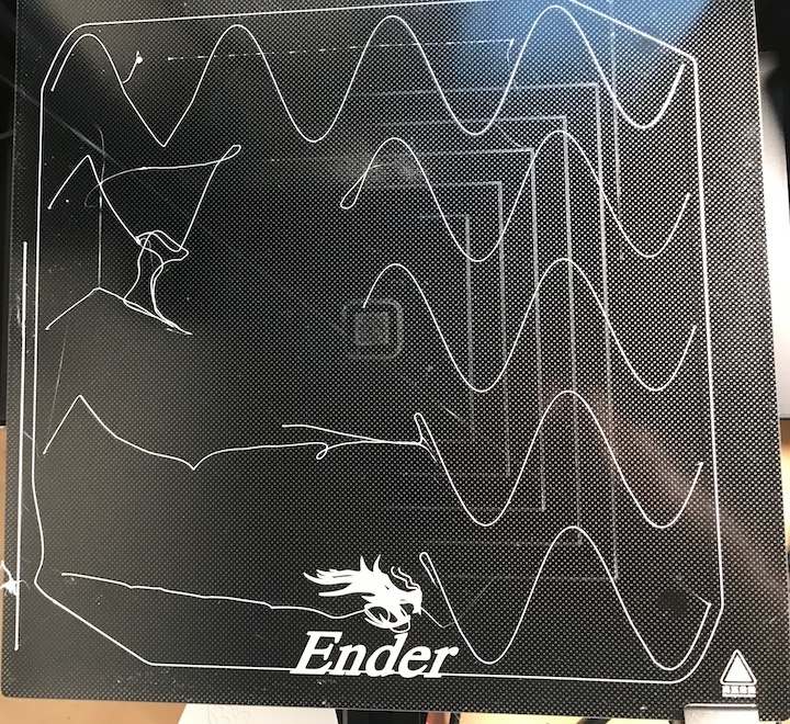
Sine wave bed leveling test
thingiverse
These 0.2mm high, 2D sine waves based on https://www.thingiverse.com/thing:11243 are for testing bed leveling and adhesion. Since the printhead is always changing direction during the sinusoidal motion, poor adhesion will show up as straight lines between where the filament tacks to the bed. This is a quick print that's fun to watch. The line widths on these traces are 0.3mm, so you may need to enable the PrusaSlicer's "PrintSettings/Layers and Perimeter/Detect Thin Walls" option or equivalent. Also included is a sinewaves.scad file for generating other sizes, shapes, and functions. I did not paste the 2dgraphing.scad content into the file to accommodate the Thingiverse customizer--I rely on OpenSCAD paths with "use" and "include". If you have a good caliper, you can measure the trace height and width of the sine waves and compare them to what your slicer is expecting. For instance, if you're slicing just doing a single, bottom layer at 0.2mm X 0.42mm, is it really 0.20mm X 0.42mm? After the fact, I added Bed Level Stripes Test" by PD_224 as a source, because the idea is similar -- a thin trace covering the area of the plate. See also https://www.printables.com/model/251587-stress-free-first-layer-calibration-in-less-than-5 -- this is an excellent method for dialing in your Z height. In making adjustments to Z, I see that the "Set home offsets" in my Ender's Marlin is related to (M290 babystepping)[https://marlinfw.org/docs/gcode/M290.html] rather than (M206 Home Offset)[https://marlinfw.org/docs/gcode/M206.html] So overall in Marlin, the Z=0 is controlled by the physical location of the endstop, the physical location/leveling of the bed, the Z_MIN_POS, M206, M290, and any probing.
With this file you will be able to print Sine wave bed leveling test with your 3D printer. Click on the button and save the file on your computer to work, edit or customize your design. You can also find more 3D designs for printers on Sine wave bed leveling test.
