Simple Microcode DSP case
thingiverse
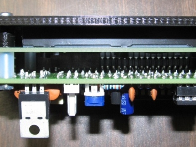
A simple test for the Microcode DSP Morse reader. Instructions: The case is straightforward, one of my earliest projects built using ViaCAD. The box features holes only for the lids, LCD display, buttons, and LED indicators. You will need to add your own drillings to securely attach the Microcode DSP to the lid, along with any necessary openings for power cables, switches, or input connectors. The case dimensions measure 113mm x 58mm x 56mm externally, while the walls are 3mm thick. The screw holes on the lid are 3mm in diameter and those on the box itself are slightly smaller at 2.5mm. To be honest, the Microcode DSP barely fits within the case. For powering the unit, I employed a LM2596 DC-DC converter capable of providing 12v DC power, which I permanently glued in place. However, one area that required additional tinkering was creating spacers to space out the Microcode DSP from the top lid, with dimensions measuring 7mm x 6mm and boasting a single 3mm hole. The DSP is ultimately held down by M2.5 x 25mm screws attached to these very spacers. Although this particular 3D model represents one of my first forays into digital modeling - admittedly imperfect, I opted to share it given its functionality, including accompanying STP and STL files created using ViaCAD v8 software.
With this file you will be able to print Simple Microcode DSP case with your 3D printer. Click on the button and save the file on your computer to work, edit or customize your design. You can also find more 3D designs for printers on Simple Microcode DSP case.
