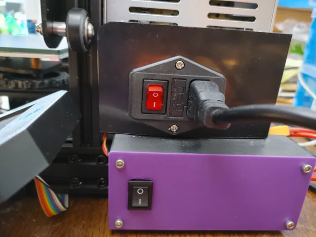
Side Relay Box with and without Switch
prusaprinters
OctoPrint allows a Raspberry Pi, or other computer, to control a 3D Printer. One of the features of OctoPrint is the ability to control power to the printer from the power supply. This requires a relay controlled by the OctoPrint computer that acts a switch on the hot wire between the power supply and the printer motherboard.This model is used to hold a relay on a 4040 rail, using t-nuts and M3 bolts. Two different covers are provided with this model. One is a solid cover and the other has a hole for a switch. The switch is optional and is used to bypass the OctoPrint control of the relay, allowing the printer to be turned on without OctoPrint.Make sure to use a relay module that your computer can control and can handle the maximum power that your printer can consume. For my case, OctoPrint runs on a Raspberry Pi and uses 3.3V for the input signal to the relay. My printer is an Ender 3 Pro and its power supply can output 24V at 14.6A so the relay needs to handle at least 350W. The relay module linked below has a power rating that handles this amount of power.Mechanical PartsThe following is a list of the non-3D printed parts that I used in my setup. This list is meant as a suggestion though using a different relay module will probably require extensive changes to the bottom box to remove the existing mount holes and aligning new mount holes for the module. Using a different size and/or shape switch will require simple changes, since the solid cover can be used as a starting point.Relay Module - Input up to 5V, Output: 30VDC at 30AT Nuts - M3 T Slot Hammer Head Fastener NutM3 x 6mm Screws Rocker SwitchPrint SettingsPrinter: Creality Ender 3 ProSupports:NoLayers:0.2 mmInfill:20%Filament:PLA+ or PLANotesThis model comes with two different covers or tops. One is a solid top that does not support the use of a switch. The other one has a hole that a 12 mm x 20 mm rocker switch can be inserted into. Only one cover is needed depending on whether a switch is used or not. Remixing:The FreeCAD file is provided for remixings. There are several cases in which remixing will be necessary.A different switch is used and it does not fit into 12 mm x 20.5 mm hole in the cover. In this case, start with the solid cover and add the appropriate size hole for your switch.A different relay is used and it does not fit the mounting holes in the bottom box. In this case, remove the existing relay mounting holes and replace them with ones that work with your relay module.If a switch is used, it may be necessary to increase the side walls of the bottom box. In my case, female disconnect connectors were used and they reached the three wires from the Raspberry Pi. I bent the connects to either side instead of redesigning and reprinting the bottom box.DesignCAD Software:FreeCAD 0.19Design Decisions:There are U shaped slots on both of the short ends of the box. This allows wires to enter and exit the box without having to worry if they fit through holes. The U shaped slots are closed when the cover is screwed into place.
With this file you will be able to print Side Relay Box with and without Switch with your 3D printer. Click on the button and save the file on your computer to work, edit or customize your design. You can also find more 3D designs for printers on Side Relay Box with and without Switch.