SherpaMicro with Dragon Hotend for X-Max (X-Plus) Linear Rail Upgrade
prusaprinters
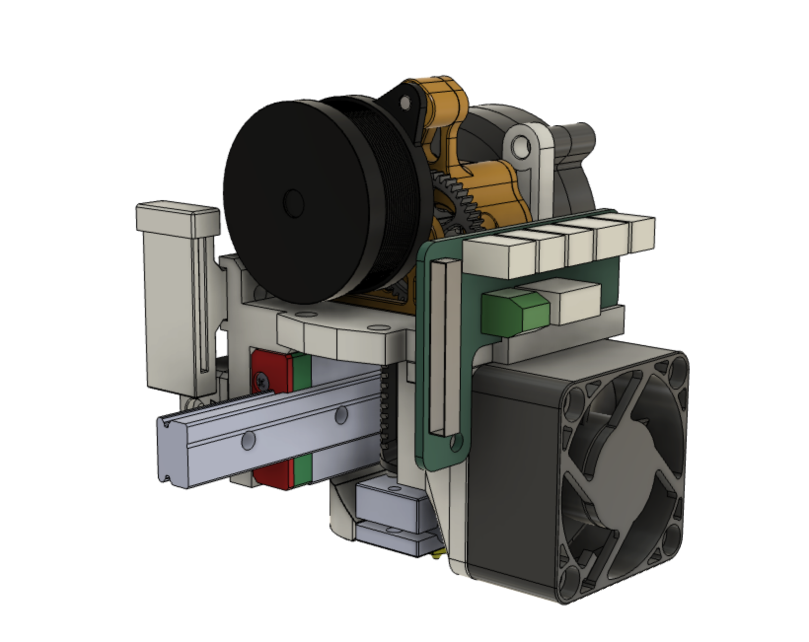
<p><strong>Description</strong></p><p>This SherpaMicro extruder and carriage setup weighs 50% less than the stock Qidi extruder/carriage resulting in better print quality.</p><p>The associated linear rail gantry files can be found here: <a href="https://www.printables.com/model/272447-x-max-x-pro-gantry-linear-rail-upgrade">https://www.printables.com/model/272447-x-max-x-pro-gantry-linear-rail-upgrade</a></p><p>The Sherpa Micro can be found here: <a href="https://github.com/Annex-Engineering/Sherpa_Micro-Extruder.">https://github.com/Annex-Engineering/Sherpa_Micro-Extruder.</a> I used this motor and parts from a BMG clone: <a href="https://a.co/d/7uWejB6">https://a.co/d/7uWejB6</a> and <a href="https://a.co/d/j71ZVnb">https://a.co/d/j71ZVnb.</a> Gear kits are also available: <a href="https://a.co/d/5c4SJLl">https://a.co/d/5c4SJLl</a></p><p>I have included the carriage STEP files to facilitate remixes and alternative extruder/hotend mounting options.</p><p><strong>Features:</strong></p><ul><li>The Layer Fan Duct snaps into place instead of using screws or magnets</li><li>The Belt Clip can be detached from carriage without disconnecting or adjusting the belt</li><li>Extruder can be removed from the carriage without detaching the carriage</li><li>A BL Touch mount and heat shield are included for those with upgraded mainboards</li><li>The ribbon guide includes a cap that pinches the ribbon for a secure fit</li></ul><p><strong>Printing:</strong></p><ul><li>All the files are designed to be printed as orientated without supports.</li><li>If you intend to print only low temp filaments, then enhanced PLA will work, otherwise Polycarbonate (PC) or PETG is needed. Carbon Fiber (CF) enhanced PC is OK, but not necessary. I do not recommend any Nylons, with or without CF, they are too flexible and prone to deformation when warmed with pressure applied.</li><li>I used 5 walls, 5 top and 5 bottom layers and 40% cubic infill with 40% overlap. All other setting adjustments were based on flow cubes and temp towers.</li><li>Use brims or mouse ear tabs to prevent warping, corner lifting, etc.</li></ul><p><strong>Post Printing:</strong></p><ul><li>The frame requires multiple brass inserts and M3 Button Head screws. Where possible it is best to push in inserts from the opposite side from which the screw will enter.</li><li>It is usually best to drill out the holes using appropriately sized bits. The set listed in the BoM below has sizes that are ideal such as 3.2mm for pass-through bolt holes.</li></ul><p><strong>Assembly:</strong></p><ul><li>The pieces go together as shown in the pictures.</li><li>The Layer Duct catch-hooks can be adjusted by filing material away or using super glue to add material back. The radial fan holds the layer duct in place. The duct has to be removed to install the carriage on the Linear Rail Bearing Guide.</li><li>The hotend is fitted with four 2.5M screws. The BoM below lists the least expensive option I could find for just these four screws.</li></ul><p><strong>Sherpa Notes:</strong></p><ul><li>I found that while the Sherpa Micro drawings call for shorter 4mm long M3 Brass inserts, that larger diameter 5.7mm long inserts fit better (see BoM below). Your results will depend on filament choice and flow settings.</li><li>The 50 tooth gear’s shaft might rub on stepper motor housing. If does use thin M3 washers to shim the motor away from the main frame.</li><li>With the motor installed, test that the gears rotate smoothly and uniformly. It is common for non-concentric gears to cause uneven rotation. This will cause surface irregularities when printing because filament pressure at the nozzle will be irregular. </li><li>The wiring colors on various Stepper motors are not consistent. Below is the easiest way I found to get the wiring sorted out.<ul><li>First identify the pairs by remove the existing JST connector and then holding the end of two wires together while turning the motor by hand, if the resistance increases when the wires are touching, it is a pair.</li><li>The pairs will be next to each other when connected to the extruder PCB connector, but which pair goes to the left and which goes to the right, and in what order do the pairs go? We answer that by trial and error.</li><li>Turn off the Printer. Connect just the PCB to the ribbon cable. Use a piece of cardboard to support the PCB on top of the printer to avoid shorts.</li><li>Remove the motor wires from the JST connector and put some heat shrink tubing on the motor's individual metal connectors.</li><li>Make a chart like this (in this case let's assume that Red and Yellow is one pair and Green and Blue is the other):<ul><li>Red, Green, Yellow, Blue</li><li>Green, Red, Yellow, Blue</li><li>Green, Red, Blue, Yellow</li><li>Red, Green, Blue, Yellow</li><li>Yellow, Blue, Red, Green</li><li>Blue, Yellow, Red, Green</li><li>Blue, Yellow, Green, Red</li><li>Yellow, Blue, Green, Red</li></ul></li><li>Connect the pairs to the PCB JST connector.</li><li>Turn on the printer and go to the filament loading option.</li><li>Click the up and down options and note the results. Positioning the motor so the gear is up, pressing the down arrow should result in clockwise rotation and up should be counter clockwise. If both arrows result in the same direction then switch one pair. If the gear goes in two directions, but up is down and down is up, then swap the pairs.</li><li>Remove the shrink wrap and install into the JST connector. Postpone cutting the wires to length until after testing with filament.</li></ul></li></ul><p>For help with connectors, I found this YouTube covers the topic nicely: </p><figure class="media"><oembed url="https://youtu.be/GZOh1NzqzzU"></oembed></figure><p><strong>BoM:</strong></p><figure class="table" style="height:1019.19px;width:714px;"><table style="border:1px double var(--input-border);"><tbody><tr><td style="border:1px solid rgb(191, 191, 191);padding:0.4em;vertical-align:top;"><strong>Description</strong></td><td style="border:1px solid rgb(191, 191, 191);padding:0.4em;vertical-align:top;"><strong>Amazon U.S.</strong></td><td style="border:1px solid rgb(191, 191, 191);padding:0.4em;vertical-align:top;width:250px;"><strong>Image</strong></td></tr><tr><td>Metric Drill Bit Set</td><td><a href="https://a.co/d/8EV6X1P">https://a.co/d/8EV6X1P</a></td><td><figure class="image image-style-align-center image_resized" style="width:75%;"><img src="https://m.media-amazon.com/images/I/71Zx9jhf-oL._SL1500_.jpg"></figure></td></tr><tr><td style="border:1px solid rgb(191, 191, 191);padding:0.4em;vertical-align:top;">M3 4.6mm x 5.7mm Threaded Brass Insert</td><td style="border:1px solid rgb(191, 191, 191);padding:0.4em;vertical-align:top;"><a href="https://a.co/d/6rNIbp1">https://a.co/d/6rNIbp1</a></td><td style="border:1px solid rgb(191, 191, 191);padding:0.4em;vertical-align:top;"><figure class="image image-style-align-center image_resized" style="width:118.102px;"><img src="https://m.media-amazon.com/images/W/WEBP_402378-T2/images/I/41L4D-4Zi4L.jpg"></figure></td></tr><tr><td>M3 4.6mm x 5.7mm Threaded Brass Insert (larger diameter despite listed specs)</td><td><a href="https://a.co/d/c4CsCfl">https://a.co/d/c4CsCfl</a></td><td><figure class="image image-style-align-center image_resized" style="width:75%;"><img src="https://m.media-amazon.com/images/I/717FLpYr9UL._SL1500_.jpg"></figure></td></tr><tr><td>M3 4.6mm x 4.0mm Threaded Brass Insert </td><td><a href="https://a.co/d/1BdwNac">https://a.co/d/1BdwNac</a></td><td><figure class="image image_resized" style="width:75%;"><img src="https://m.media-amazon.com/images/I/41F2jKSvjRL.jpg"></figure></td></tr><tr><td>M2.5 Hex Button Head Socket Cap Screws</td><td><a href="https://a.co/d/h7VmDYD">https://a.co/d/h7VmDYD</a></td><td><figure class="image image-style-align-center image_resized" style="width:75%;"><img src="https://m.media-amazon.com/images/I/81IRVrowpjL._SL1500_.jpg"></figure></td></tr><tr><td>M3 Hex Button Head Socket Cap Screws</td><td><a href="https://a.co/d/9ZLzOGI">https://a.co/d/9ZLzOGI</a></td><td><figure class="image image-style-align-center image_resized" style="width:75%;"><img src="https://m.media-amazon.com/images/I/81Ky-2ebEwL._SL1500_.jpg"></figure></td></tr><tr><td style="border:1px solid rgb(191, 191, 191);padding:0.4em;vertical-align:top;">M3 Hex Socket Head Cap Screws</td><td style="border:1px solid rgb(191, 191, 191);padding:0.4em;vertical-align:top;"><a href="https://a.co/d/1ef5smv">https://a.co/d/1ef5smv</a></td><td style="border:1px solid rgb(191, 191, 191);padding:0.4em;vertical-align:top;"><figure class="image image-style-align-center image_resized" style="width:75%;"><img src="https://m.media-amazon.com/images/W/WEBP_402378-T2/images/I/81WcTT23O2L._SL1500_.jpg"></figure></td></tr><tr><td>LDO NEMA14 36mm Round Pancake Motor LDO-36STH20-1004AHG(XH)</td><td><a href="https://a.co/d/6OWsnAP">https://a.co/d/6OWsnAP</a></td><td><figure class="image image-style-align-center image_resized" style="width:75%;"><img src="https://m.media-amazon.com/images/I/71f0uONWOBL._SL1500_.jpg"></figure></td></tr><tr><td>Universal Geared Extruder Dual Drive Extruder</td><td><a href="https://a.co/d/1O1lELS">https://a.co/d/1O1lELS</a></td><td><figure class="image image_resized" style="width:75%;"><img src="https://m.media-amazon.com/images/I/41UP7KUcDnL._AC_.jpg"></figure></td></tr><tr><td>Dual Direct Drive Basic Kit</td><td><a href="https://a.co/d/9cwiG5c">https://a.co/d/9cwiG5c</a></td><td><figure class="image image_resized" style="width:75%;"><img src="https://m.media-amazon.com/images/I/51+45bx7NzL._SL1000_.jpg"></figure></td></tr></tbody></table></figure>
With this file you will be able to print SherpaMicro with Dragon Hotend for X-Max (X-Plus) Linear Rail Upgrade with your 3D printer. Click on the button and save the file on your computer to work, edit or customize your design. You can also find more 3D designs for printers on SherpaMicro with Dragon Hotend for X-Max (X-Plus) Linear Rail Upgrade.